CAN COMMUNICATION SYSTEM ECM Communication Stop Mode
DESCRIPTION
| Detection Item | Symptom | Trouble Area |
|---|---|---|
| ECM Communication Stop Mode |
|
|
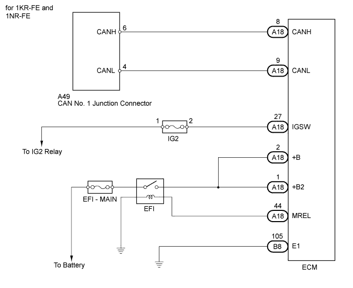
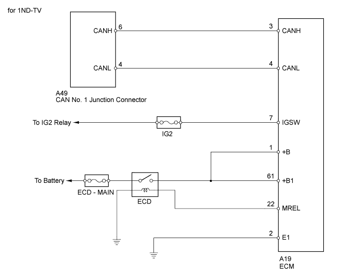
WIRING DIAGRAM
INSPECTION PROCEDURE
Note
-
Inspect the fuses for circuit related to this system before performing the following inspection procedure.
-
Turn the ignition switch off before measuring the resistances of the CAN main wire and the CAN branch wire.
-
After the ignition switch is turned off, check that the key reminder warning system and light reminder warning system are not in operation.
-
Before measuring the resistance, leave the vehicle as is for at least 1 minute and do not operate the ignition switch, any other switches or the doors. If doors need to be opened in order to check connectors, open the doors and leave them open.
Tech Tips
Operating the ignition switch, any switches or any doors triggers related ECU and sensor communication with the CAN, which causes resistance variation.
PROCEDURE
-
SYSTEM CHECK
-
Check the vehicle specifications.
Result Result Proceed to for 1KR-FE engine and 1NR-FE engine A for 1ND-TV engine B
B 
CHECK FOR OPEN IN CAN BUS WIRE (ECM MAIN WIRE) Click here
A 
-
-
CHECK FOR OPEN IN CAN BUS WIRE (ECM MAIN WIRE)
-
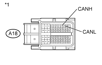
Text in Illustration *1 Front view of wire harness connector
(to ECM)
Turn the ignition switch off.
-
Disconnect the A18 ECM connector.
-
Measure the resistance according to the value(s) in the table below.
Standard Resistance Tester Connection Switch Condition Specified Condition A18-8 (CANH) - A18-9 (CANL) Ignition switch off 108 to 132 Ω -
Reconnect the ECM connector.
NG 
REPAIR OR REPLACE CAN MAIN WIRE OR CONNECTOR (CAN-H, CAN-L)
OK
-
-
CHECK HARNESS AND CONNECTOR (ECM - BATTERY AND BODY GROUND)
-
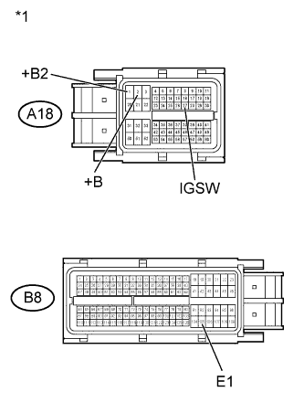
Text in Illustration *1 Front view of wire harness connector
(to ECM)
Disconnect the A18 and B8 ECM connector.
-
Measure the resistance according to the value(s) in the table below.
Standard Resistance Tester Connection Condition Specified Condition B8-105 (E1) - Body ground Always Below 1 Ω -
Measure the voltage according to the value(s) in the table below.
Standard Voltage Tester Connection Switch Condition Specified Condition A18-27 (IGSW) - Body ground Ignition switch ON 11 to 14 V A18-2 (+B) - Body ground Ignition switch ON 11 to 14 V A18-1 (+B2) - Body ground Ignition switch ON 11 to 14 V -
Reconnect the ECM connectors.
Result Result Proceed to NG A OK (for 1KR-FE engine) B OK (for 1NR-FE engine) C
B
REPLACE ECM Click here
C
REPLACE ECM Click here
A 
REPAIR OR REPLACE HARNESS OR CONNECTOR
-
-
CHECK FOR OPEN IN CAN BUS WIRE (ECM MAIN WIRE)
-
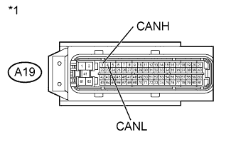
Text in Illustration *1 Front view of wire harness connector
(to ECM)
Turn the ignition switch off.
-
Disconnect the A19 ECM connector.
-
Measure the resistance according to the value(s) in the table below.
Standard Resistance Tester Connection Switch Condition Specified Condition A19-3 (CANH) - A19-4 (CANL) Ignition switch off 108 to 132 Ω -
Reconnect the ECM connector.
NG
REPAIR OR REPLACE CAN MAIN WIRE OR CONNECTOR (CAN-H, CAN-L)
OK
-
-
CHECK HARNESS AND CONNECTOR (ECM - BATTERY AND BODY GROUND)
-
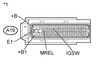
Text in Illustration *1 Front view of wire harness connector
(to ECM)
Disconnect the A19 ECM connector.
-
Measure the resistance according to the value(s) in the table below.
Standard Resistance Tester Connection Condition Specified Condition A19-2 (E1) - Body ground Always Below 1 Ω -
Measure the voltage according to the value(s) in the table below.
Standard Voltage Tester Connection Switch Condition Specified Condition A19-7 (IGSW) - Body ground Ignition switch ON 11 to 14 V A19-1 (+B) - Body ground Ignition switch ON 11 to 14 V A19-61 (+B1) - Body ground Ignition switch ON 11 to 14 V -
Reconnect the ECM connector.
NG
REPAIR OR REPLACE HARNESS OR CONNECTOR
OK
REPLACE ECM Click here
-