CAN COMMUNICATION SYSTEM, Diagnostic DTC:U1002

| DTC Code | DTC Name |
|---|---|
| U1002 | Lost Communication with Gateway Module |
DESCRIPTION
-
The power management control ECU* will store this DTC when no signals can be received from the ECUs that have been memorized as those are connected to the power management bus.
-
When the power management control ECU* receives a response signal from the ECUs connected to the power management bus, the power management control ECU* recognizes and memorizes that the ECU is connected to the power management bus. Based on this memorized data, the power management control ECU* monitors for malfunctions in the ECUs connected to the power management bus when communicating with those ECUs. If the power management control ECU* cannot receive response signals from the ECUs that have been memorized as those connected to the power management bus, the power management control ECU* determines that a malfunction exists.
| DTC No. | DTC Detection Condition | Trouble Area |
|---|---|---|
| U1002 | Power management control ECU* cannot receive signals from all ECUs that have been memorized as those connected to the power management bus. |
|
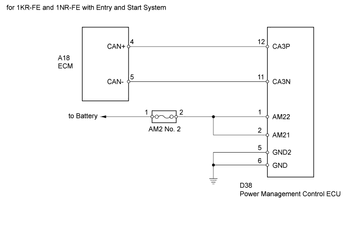
*: for 1KR-FE and 1NR-FE with Entry and Start System
WIRING DIAGRAM
INSPECTION PROCEDURE
Note
-
Inspect the fuses for circuit related to this system before performing the following inspection procedure.
-
Turn the ignition switch off before measuring the resistances of the power management bus wire.
-
After the ignition switch is turned off, check that the key reminder warning system and light reminder warning system are not in operation.
-
Before measuring the resistance, leave the vehicle as is for at least 1 minute and do not operate the ignition switch, any other switches or the doors. If doors need to be opened in order to check connectors, open the doors and leave them open.
Tech Tips
Operating the ignition switch, any switches or any doors triggers related ECU and sensor communication with the CAN, which causes resistance variation.
PROCEDURE
-
CHECK CAN BUS WIRE (ECM - POWER MANAGEMENT CONTROL ECU)
-
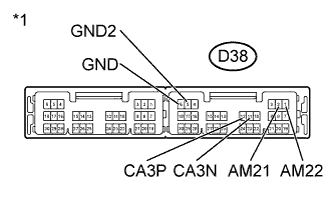
Text in Illustration *1 Compartment with harness connected
(Power Management Control ECU)
Measure the resistance according to the value(s) in the table below.
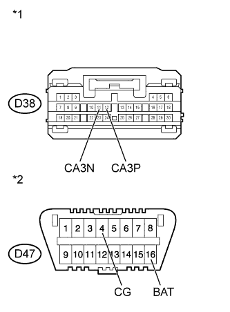
Standard Resistance Tester Connection Switch Condition Specified Condition D38-12 (CA3P) - D38-11 (CA3N) Ignition switch off 54 to 69 Ω Result Result Proceed to NG
(70 Ω or higher)
A NG
(53 Ω or less)
B OK C Standard Resistance Tester Connection Switch Condition Specified Condition D38-12 (CA3P) - D38-1 (AM22) or D38-2 (AM21) Ignition switch off 6 kΩ or higher D38-11 (CA3N) - D38-1 (AM22) or D38-2 (AM21) Ignition switch off 6 kΩ or higher Result Result Proceed to NG B OK C Standard Resistance Tester Connection Switch Condition Specified Condition D38-12 (CA3P) - D38-5 (GND2) or D38-6 (GND) Ignition switch off 200 Ω or higher D38-11 (CA3N) - D38-5 (GND2) or D38-6 (GND) Ignition switch off 200 Ω or higher Result Result Proceed to NG B OK C
B 
CHECK FOR SHORT IN CAN BUS WIRE (POWER MANAGEMENT CONTROL ECU) Click here
C
CHECK HARNESS AND CONNECTOR (POWER MANAGEMENT CONTROL ECU - BATTERY AND BODY GROUND) Click here
A 
-
-
CHECK FOR OPEN IN CAN BUS WIRE (POWER MANAGEMENT CONTROL ECU)
-
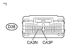
Text in Illustration *1 Front view of wire harness connector
(to Power Management Control ECU)
Disconnect the D38 power management control ECU connector.
-
Measure the resistance according to the value(s) in the table below.
Standard Resistance Tester Connection Switch Condition Specified Condition D38-12 (CA3P) - D38-11 (CA3N) Ignition switch off 108 to 132 Ω
NG
CONNECT CONNECTOR Click here
OK 
REPLACE POWER MANAGEMENT CONTROL ECU Click here
-
-
CONNECT CONNECTOR
-
Reconnect the power management control ECU connector.
NEXT
-
-
CHECK FOR OPEN IN CAN BUS WIRE (ECM)
-
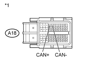
Text in Illustration *1 Front view of wire harness connector
(to ECM)
Disconnect the A18 ECM connector.
-
Measure the resistance according to the value(s) in the table below.
Standard Resistance Tester Connection Switch Condition Specified Condition A18-4 (CAN+) - A18-5 (CAN-) Ignition switch off 108 to 132 Ω Result Result Proceed to NG A OK (for 1KR-FE engine) B OK (for 1NR-FE engine) C
B 
REPLACE ECM Click here
C
REPLACE ECM Click here
A
REPAIR OR REPLACE CAN MAIN WIRE OR CONNECTOR (CAN-H, CAN-L)
-
-
CHECK FOR SHORT IN CAN BUS WIRE (POWER MANAGEMENT CONTROL ECU)
-
Text in Illustration *1 Front view of wire harness connector
(to Power Management Control ECU)
*2 Front view of DLC3 Disconnect the D38 power management control ECU connector.
-
Measure the resistance according to the value(s) in the table below.
Standard Resistance Tester Connection Switch Condition Specified Condition D38-12 (CA3P) - D38-11 (CA3N) Ignition switch off 108 to 132 Ω D38-12 (CA3P) - D47-16 (BAT) Ignition switch off 6 kΩ or higher D38-11 (CA3N) - D47-16 (BAT) Ignition switch off 6 kΩ or higher D38-12 (CA3P) - D47-4 (CG) Ignition switch off 200 Ω or higher D38-11 (CA3N) - D47-4 (CG) Ignition switch off 200 Ω or higher
NG
CONNECT CONNECTOR Click here
OK
REPLACE POWER MANAGEMENT CONTROL ECU Click here
-
-
CONNECT CONNECTOR
-
Reconnect the power management control ECU connector.
NEXT
-
-
CHECK FOR SHORT IN CAN BUS WIRE (ECM)
-
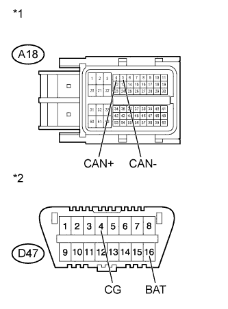
Text in Illustration *1 Front view of wire harness connector
(to ECM)
*2 Front view of DLC3 Disconnect the A18 ECM connector.
-
Measure the resistance according to the value(s) in the table blow.
Standard Resistance Tester Connection Switch Condition Specified Condition A18-4 (CAN+) - A18-5 (CAN-) Ignition switch off 108 to 132 Ω A18-4 (CAN+) - D47-16 (BAT) Ignition switch off 6 kΩ or higher A18-5 (CAN-) - D47-16 (BAT) Ignition switch off 6 kΩ or higher A18-4 (CAN+) - D47-4 (CG) Ignition switch off 200 Ω or higher A18-5 (CAN-) - D47-4 (CG) Ignition switch off 200 Ω or higher Result Result Proceed to NG A OK (for 1KR-FE engine) B OK (for 1NR-FE engine) C
B
REPLACE ECM Click here
C
REPLACE ECM Click here
A
REPAIR OR REPLACE CAN MAIN WIRE OR CONNECTOR (CAN-H, CAN-L)
-
-
CHECK HARNESS AND CONNECTOR (POWER MANAGEMENT CONTROL ECU - BATTERY AND BODY GROUND)
-
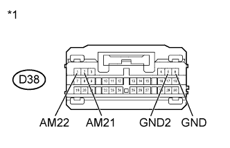
Text in Illustration *1 Front view of wire harness connector
(to Power Management Control ECU)
Disconnect the D38 power management control ECU connector.
-
Measure the resistance according to the value(s) in the table below.
Standard Resistance Tester Connection Condition Specified Condition D38-5 (GND2) - Body ground Always Below 1 Ω D38-6 (GND) - Body ground Always Below 1 Ω -
Measure the voltage according to the value(s) in the table below.
Standard Voltage Tester Connection Condition Specified Condition D38-2 (AM21) - Body ground Always 11 to 14 V D38-1 (AM22) - Body ground Always 11 to 14 V
NG
REPAIR OR REPLACE HARNESS OR CONNECTOR
OK
REPLACE POWER MANAGEMENT CONTROL ECU Click here
-