CONTINUOUSLY VARIABLE TRANSAXLE SYSTEM, Diagnostic DTC:P2767
| DTC Code | DTC Name |
|---|---|
| P2767 | Input / Turbine Speed Sensor "B" Circuit No Signal |
DESCRIPTION
The ECM detects the input shaft rotation speed based on the signal from the primary pulley speed sensor (transmission revolution sensor NIN) and performs gear ratio change control.
| DTC No. | DTC Detection Condition
|
Trouble Area |
|---|---|---|
| P2767 |
|
|
MONITOR DESCRIPTION
The ECM receives a signal from the primary pulley speed sensor (transmission revolution sensor (NIN)) installed in the continuously variable transaxle and determines the input shaft speed in order to control the gear ratio. If the ECM detects no signal from the primary pulley speed sensor even while the vehicle is moving, it will conclude that there is a malfunction in the primary pulley speed sensor. The ECM will illuminate the MIL and set the DTC.
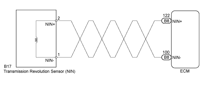
WIRING DIAGRAM
INSPECTION PROCEDURE
PROCEDURE
-
READ VALUE USING INTELLIGENT TESTER (SPD (NIN))
-
Connect the intelligent tester to the DLC3.
-
Turn the ignition switch to ON.
-
Turn the tester on.
-
Enter the following menus: Powertrain / Engine and ECT / Data List.
-
In accordance with the display on the tester, read the Data List.
Tester Display Measurement Item/
Range (display)
Normal Condition Diagnostic Note SPD (NIN) Primary pulley speed (NIN)/
Display: 50 rpm
min.: 0 rpm
max.: 12750 rpm
-
Vehicle stopped: 0 rpm
-
Lock-up ON (After warming up engine): Primary pulley speed (NIN) equal to engine speed
- Result Result Proceed to Data display is not within Normal Condition range A Data display is within Normal Condition range B -
B 
REPLACE ECM Click here
A 
-
-
INSPECT TRANSMISSION REVOLUTION SENSOR (NIN)
-
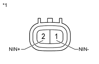
Text in Illustration *1 Component without wire harness connected:
(Transmission Revolution Sensor (NIN))
Remove the transmission revolution sensor (NIN) Click here.
-
Measure the resistance according to the value(s) in the table below.
Standard Resistance Tester Connection Condition Specified Condition 1 (NIN-) - 2 (NIN+) 20°C (68°F) 560 to 680 Ω
NG 
REPLACE TRANSMISSION REVOLUTION SENSOR (NIN) Click here
OK
-
-
CHECK HARNESS AND CONNECTOR (TRANSMISSION REVOLUTION SENSOR (NIN) - ECM)
-
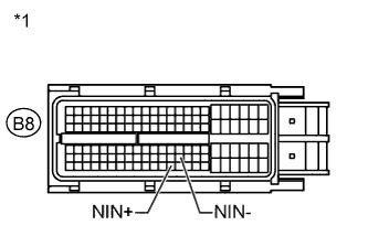
Text in Illustration *1 Front view of wire harness connector:
(to ECM)
Reconnect the transmission revolution sensor (NIN) connector.
-
Disconnect the ECM connector.
-
Measure the resistance according to the value(s) in the table below.
Standard Resistance Tester Connection Condition Specified Condition B8-122 (NIN+) - B8-100 (NIN-) 20°C (68°F) 560 to 680 Ω
NG
REPAIR OR REPLACE HARNESS OR CONNECTOR
OK
-
-
REPLACE ECM
-
Replace the ECM Click here.
NEXT
-
-
PERFORM INITIALIZATION
-
Perform the initialization Click here.
-
Check for DTCs again Click here.
NEXT 
END
-