CONTINUOUSLY VARIABLE TRANSAXLE SYSTEM, Diagnostic DTC:P282B
| DTC Code | DTC Name |
|---|---|
| P282B | Pressure Control Solenoid "K" Electrical (Shift Solenoid Valve SLS) |
DESCRIPTION
The ECM uses the SLS solenoid valve to control the secondary pulley pressure and belt clamping pressure according to the input shaft torque force. Additionally, solenoid SLS is used to control the forward clutch hydraulic pressure when the forward clutch is engaged and the neutral control is operating.
| DTC No. | DTC Detection Condition
|
Trouble Area |
|---|---|---|
| P282B |
|
|
MONITOR DESCRIPTION
These DTCs indicate an open or short in the belt clamping pressure liner solenoid SLS circuit. When there is an open or short circuit in any belt clamping pressure liner solenoid valve circuits, the ECM detects the problem, illuminates the MIL and stores the DTC.
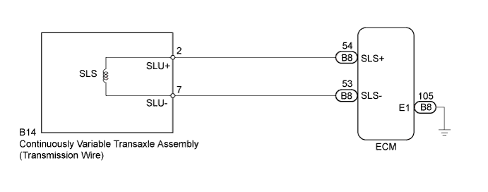
WIRING DIAGRAM
INSPECTION PROCEDURE
PROCEDURE
-
INSPECT CONTINUOUSLY VARIABLE TRANSAXLE ASSEMBLY (BELT CLAMPING PRESSURE LINER SOLENOID SLS)
-
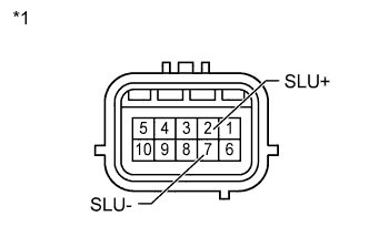
Text in Illustration *1 Component without wire harness connected:
(Continuously Variable Transaxle Assembly
(Transmission Wire))
Disconnect the transmission wire connector from the transaxle.
-
Measure the resistance according to the value(s) in the table below.
Standard Resistance Tester Connection Condition Specified Condition 2 (SLU+) - 7 (SLU-) 20°C (68°F) 5.0 to 5.6 Ω
NG 
REPLACE CONTINUOUSLY VARIABLE TRANSAXLE ASSEMBLY Click here
OK 
-
-
CHECK HARNESS AND CONNECTOR (TRANSMISSION WIRE - ECM)
-
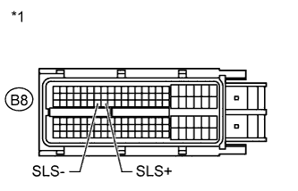
Text in Illustration *1 Front view of wire harness connector:
(to ECM)
Reconnect the transmission wire connector.
-
Disconnect the ECM connector.
-
Measure the resistance according to the value(s) in the table below.
Standard Resistance Tester Connection Condition Specified Condition B8-54 (SLU+) - B8-53 (SLU-) 20°C (68°F) 5.0 to 5.6 Ω
NG 
REPAIR OR REPLACE HARNESS OR CONNECTOR
OK
-
-
REPLACE ECM
-
Replace ECM Click here.
NEXT
-
-
PERFORM INITIALIZATION
Note
-
Performing reset memory/initialization will clear the learned values of both the yaw rate and acceleration sensor (deceleration sensor 0 point calibration) and the CVT oil pressure (CVT oil pressure calibration). Make sure to perform reset memory, yaw rate and acceleration sensor 0 point calibration, and CVT oil pressure calibration when replacing any of the parts shown in the following table:
Replaced Part
-
Continuously variable transaxle assembly
-
ECM
-
Oil pressure sensor
-
Yaw rate and acceleration sensor
-
-
After reset memory, always perform yaw rate and acceleration sensor (deceleration sensor 0 point) calibration first, and then the CVT oil pressure calibration.
-
Always perform the 0 point calibration with the vehicle on level ground.
-
Do not shake or vibrate the vehicle during the 0 point calibration.
-
Using the intelligent tester, perform the reset memory, deceleration sensor 0 point calibration and CVT oil pressure calibration Click here.
-
Check for DTCs again Click here.
NEXT 
END
-
-
REPLACE CONTINUOUSLY VARIABLE TRANSAXLE ASSEMBLY
-
Replace continuously variable transaxle assembly Click here.
NEXT
-
-
PERFORM INITIALIZATION
Note
-
Performing reset memory/initialization will clear the learned values of both the yaw rate and acceleration sensor (deceleration sensor 0 point calibration) and the CVT oil pressure (CVT oil pressure calibration). Make sure to perform reset memory, yaw rate and acceleration sensor 0 point calibration, and CVT oil pressure calibration when replacing any of the parts shown in the following table:
Replaced Part
-
Continuously variable transaxle assembly
-
ECM
-
Oil pressure sensor
-
Yaw rate and acceleration sensor
-
-
After reset memory, always perform yaw rate and acceleration sensor (deceleration sensor 0 point) calibration first, and then the CVT oil pressure calibration.
-
Always perform the 0 point calibration with the vehicle on level ground.
-
Do not shake or vibrate the vehicle during the 0 point calibration.
-
Using the intelligent tester, perform the reset memory, deceleration sensor 0 point calibration and CVT oil pressure calibration Click here.
-
Check for DTCs again Click here.
NEXT
END
-