CONTINUOUSLY VARIABLE TRANSAXLE SYSTEM, Diagnostic DTC:P0705
| DTC Code | DTC Name |
|---|---|
| P0705 | Transmission Range Sensor Circuit Malfunction (PRNDL Input) |
DESCRIPTION
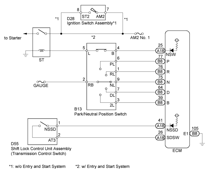
The park/neutral position switch and shift lock control unit assembly (transmission control switch) detect the shift lever position and send signals to the ECM.
| DTC No. | DTC Detection Condition
|
Trouble Area |
|---|---|---|
| P0705 |
|
|
|
||
|
MONITOR DESCRIPTION
For security, the park/neutral position switch detects the gearshift position so that engine can be started only when the vehicle is in the P or N shift position.
When the park/neutral position switch and shift lock control unit assembly (transmission control switch) send more than one signal at a time from switch positions P, R, N, D, S (SDSW) or B, the ECM interprets this as a fault in the switch. The ECM will turn on the MIL and store the DTC.
WIRING DIAGRAM
INSPECTION PROCEDURE
Note
Inspect the fuses for circuits related to this system before performing the following inspection procedure.
PROCEDURE
-
READ VALUE USING INTELLIGENT TESTER (NEUTRAL POSITION SW SIGNAL AND SHIFT SW STATUS)
-
Connect the intelligent tester to the DLC3.
-
Turn the ignition switch to ON.
-
Turn the tester on.
-
Enter the following menus: Powertrain / Engine and ECT / Data List.
-
In accordance with the display on the tester, read the Data List.
Tester Display Measurement Item/Range Normal Condition Diagnostic Note Neutral Position SW Signal PNP switch status/
ON or OFF
Shift lever position;
P or N: ON
Except P and N: OFF
When shift lever position displayed on intelligent tester differs from actual position, adjustment of PNP switch or shift cable may be incorrect. Shift SW Status (R Range) PNP switch status/
ON or OFF
Shift lever position;
R: ON
Except R: OFF
Shift SW Status (P Range) PNP switch status/
ON or OFF
Shift lever position;
P: ON
Except P: OFF
Shift SW Status (N Range) PNP switch status/
ON or OFF
Shift lever position;
N: ON
Except N: OFF
Shift SW Status (D Range) PNP switch status/
ON or OFF
Shift lever position;
D or S: ON
Except D and S: OFF
Shift SW Status (B Range) PNP switch status/
ON or OFF
Shift lever position;
B: ON
Except B: OFF
Result Result Proceed to Data display is within Normal Condition range A Data display is not within Normal Condition range B
B 
CHECK HARNESS AND CONNECTOR (BATTERY - PARK/NEUTRAL POSITION SWITCH) Click here
A 
-
-
READ VALUE USING INTELLIGENT TESTER (SD SWITCH)
-
Enter the following menus: Powertrain / Engine and ECT / Data List.
-
In accordance with the display on the tester, read the Data List.
Tester Display Measurement Item/Range Normal Condition Diagnostic Note SD Switch Transmission control switch status/
ON or OFF
Shift lever position;
S or B: ON
Except S and B: OFF
- Result Result Proceed to Data display is within Normal Condition range A Data display is not within Normal Condition range B
B
INSPECT SHIFT LOCK CONTROL UNIT ASSEMBLY (TRANSMISSION CONTROL SWITCH) Click here
A 
CHECK INTERMITTENT PROBLEMS Click here
-
-
INSPECT SHIFT LOCK CONTROL UNIT ASSEMBLY (TRANSMISSION CONTROL SWITCH)
-
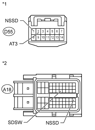
Text in Illustration *1 Component without harness connected:
(Transmission control unit assembly
(Transmission control switch))
Disconnect the transmission control switch connector of the shift lock control unit assembly.
-
Measure the resistance according to the value(s) in the table below.
Standard Resistance Tester Connection Condition Specified Condition 1 (NSSD) - 2 (AT3) Shift lever S or B position Below 1 Ω Shift lever D position 10 kΩ or higher
NG 
REPLACE SHIFT LOCK CONTROL UNIT ASSEMBLY Click here
OK
-
-
CHECK HARNESS AND CONNECTOR (SHIFT LOCK CONTROL UNIT ASSEMBLY - ECM)
-
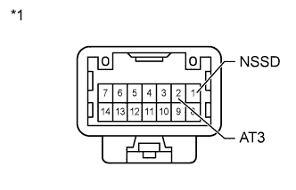
Text in Illustration *1 Front view of wire harness connector:
(to Transmission control unit assembly
(Transmission control switch))
*2 Front view of wire harness connector:
(to ECM)
Disconnect the ECM connector.
-
Measure the resistance according to the value(s) in the table below.
Standard Resistance Tester Connection Condition Specified Condition D55-1 (NSSD) - A18-41 (NSSD) Always Below 1 Ω D55-2 (AT3) - A18-26 (SDSW) Always Below 1 Ω
NG
REPAIR OR REPLACE HARNESS OR CONNECTOR
OK
-
-
REPLACE ECM
-
Replace the ECM Click here.
NEXT
-
-
PERFORM INITIALIZATION
Note
-
Performing reset memory/initialization will clear the learned values of both the yaw rate and acceleration sensor (deceleration sensor 0 point calibration) and the CVT oil pressure (CVT oil pressure calibration). Make sure to perform reset memory, yaw rate and acceleration sensor 0 point calibration, and CVT oil pressure calibration when replacing any of the parts shown in the following table:
Replaced Part
-
Continuously variable transaxle assembly
-
ECM
-
Oil pressure sensor
-
Yaw rate and acceleration sensor
-
-
After reset memory, always perform yaw rate and acceleration sensor (deceleration sensor 0 point) calibration first, and then the CVT oil pressure calibration.
-
Always perform the 0 point calibration with the vehicle on level ground.
-
Do not shake or vibrate the vehicle during the 0 point calibration.
-
Using the intelligent tester, perform the reset memory, deceleration sensor 0 point calibration and CVT oil pressure calibration Click here.
-
Check for DTCs again Click here.
NEXT
END
-
-
CHECK HARNESS AND CONNECTOR (BATTERY - PARK/NEUTRAL POSITION SWITCH)
-
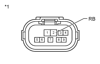
Text in Illustration *1 Front view of wire harness connector:
(to Park/Neutral Position Switch)
Disconnect the park/neutral position switch connector.
-
Turn the ignition switch to ON.
-
Measure the voltage according to the value(s) in the table below.
Standard Voltage Tester Connection Switch Condition Specified Condition C27-2 (RB) - Body ground Ignition switch ON 11 to 14 V Ignition switch off Below 1 V
NG
REPAIR OR REPLACE HARNESS OR CONNECTOR
OK
-
-
INSPECT PARK/NEUTRAL POSITION SWITCH ASSEMBLY
-
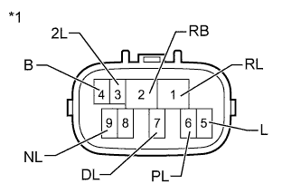
Text in Illustration *1 Component without harness connected:
(Park/Neutral Position Switch)
Disconnect the park/neutral position switch connector.
-
Measure the resistance according to the value(s) in the table below.
Standard Resistance Tester Connection Condition Specified Condition 4 (B) - 5 (L) Shift lever P or N position Below 1 Ω Shift lever other than P and N position 10 kΩ or higher 2 (RB) - 6 (PL) Shift lever P position Below 1 Ω Shift lever other than P position 10 kΩ or higher 1 (RL) - 2 (RB) Shift lever R position Below 1 Ω Shift lever other than R position 10 kΩ or higher 2 (RB) - 9 (NL) Shift lever N position Below 1 Ω Shift lever other than N position 10 kΩ or higher 2 (RB) - 7 (DL) Shift lever D or S position Below 1 Ω Shift lever other than D and S position 10 kΩ or higher 2 (RB) - 3 (2L) Shift lever B position Below 1 Ω Shift lever other than B position 10 kΩ or higher
NG
REPLACE PARK/NEUTRAL POSITION SWITCH ASSEMBLY Click here
OK
-
-
CHECK HARNESS AND CONNECTOR (PARK/NEUTRAL POSITION SWITCH - ECM)
-
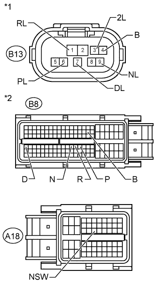
Text in Illustration *1 Front view of wire harness connector:
(to Park/Neutral Position Switch)
*2 Front view of wire harness connector:
(to ECM)
Disconnect the ECM connectors.
-
Measure the resistance according to the value(s) in the table below.
Standard Resistance Tester Connection Condition Specified Condition B13-1 (RL) - B8-76 (R) Always Below 1 Ω B13-3 (2L) - B8-39 (B) Always Below 1 Ω B13-4 (B) - A18-25 (NSW) Always Below 1 Ω B13-6 (PL) - B8-77 (P) Always Below 1 Ω B13-7 (DL) - B8-64 (D) Always Below 1 Ω B13-9 (NL) - B8-75 (N) Always Below 1 Ω A18-25 (NSW) - Body ground Always 10 kΩ or higher B8-39 (B) - Body ground Always 10 kΩ or higher B8-64 (D) - Body ground Always 10 kΩ or higher B8-75 (N) - Body ground Always 10 kΩ or higher B8-76 (R) - Body ground Always 10 kΩ or higher B8-77 (P) - Body ground Always 10 kΩ or higher
NG
REPAIR OR REPLACE HARNESS OR CONNECTOR
OK
-
-
REPLACE ECM
-
Replace the ECM Click here.
NEXT
-
-
PERFORM INITIALIZATION
Note
-
Performing reset memory/initialization will clear the learned values of both the yaw rate and acceleration sensor (deceleration sensor 0 point calibration) and the CVT oil pressure (CVT oil pressure calibration). Make sure to perform reset memory, yaw rate and acceleration sensor 0 point calibration, and CVT oil pressure calibration when replacing any of the parts shown in the following table:
Replaced Part
-
Continuously variable transaxle assembly
-
ECM
-
Oil pressure sensor
-
Yaw rate and acceleration sensor
-
-
After reset memory, always perform yaw rate and acceleration sensor (deceleration sensor 0 point) calibration first, and then the CVT oil pressure calibration.
-
Always perform the 0 point calibration with the vehicle on level ground.
-
Do not shake or vibrate the vehicle during the 0 point calibration.
-
Using the intelligent tester, perform the reset memory, deceleration sensor 0 point calibration and CVT oil pressure calibration Click here.
-
Check for DTCs again Click here.
NEXT
END
-