CAMSHAFT REMOVAL

-
INSTALL ENGINE STAND
-
REMOVE ENGINE HANGER
-
Remove the 2 bolts and 2 engine hangers.
-
-
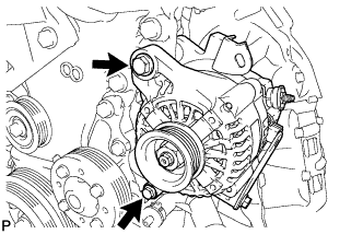
REMOVE GENERATOR ASSEMBLY
-
Remove the 2 bolts and the generator.
-
-
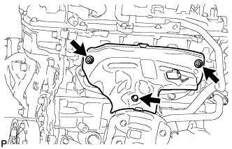
REMOVE NO. 1 EXHAUST MANIFOLD HEAT INSULATOR
-
Remove the bolt, 2 nuts and the No. 1 exhaust manifold heat insulator.
-
-
REMOVE MANIFOLD STAY

-
Remove the bolt, nut and the manifold stay.
-
-
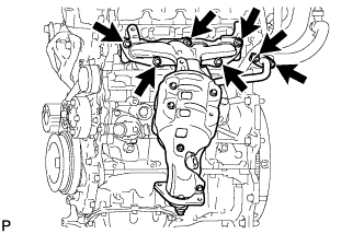
REMOVE EXHAUST MANIFOLD CONVERTER SUB-ASSEMBLY
-
Remove the 3 bolts, 4 nuts and the exhaust manifold converter.
-
Remove the exhaust manifold to head gasket and inlet EGR gasket from the cylinder head.
-
-
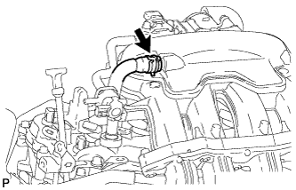
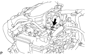
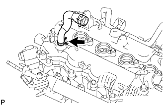
DISCONNECT VENTILATION HOSE
-
Loosen the clip and disconnect the ventilation hose from the intake manifold.
-
-
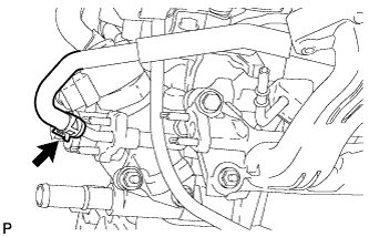
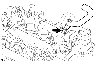
DISCONNECT NO. 2 WATER BY-PASS HOSE
-
Loosen the clip and disconnect the No. 2 water by-pass hose from the throttle body.
-
-
DISCONNECT NO. 4 WATER BY-PASS HOSE
-
Loosen the clip and disconnect the No. 4 water by-pass hose from the EGR valve.
-
-
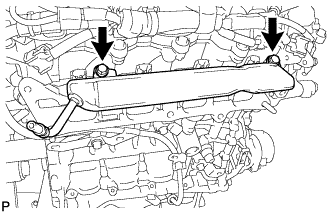
REMOVE INTAKE MANIFOLD STAY

-
Remove the 2 bolts and the intake manifold stay.
-
-
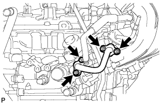
REMOVE EGR PIPE CONNECTOR
-
Remove the 4 nuts and the EGR pipe connector.
-
Remove the 2 EGR pipe gaskets from the intake manifold and EGR valve.
-
-
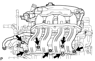
REMOVE INTAKE MANIFOLD ASSEMBLY
-
Remove the 5 bolts, 2 nuts and the intake manifold.
-
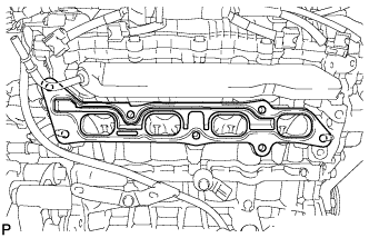
Remove the intake manifold to head gasket from the cylinder head.
-
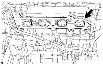
Remove the EGR delivery chamber from the cylinder head.
-
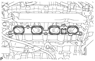
Remove the No. 2 intake manifold to head gasket from the cylinder head.
-
-
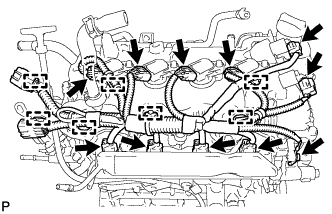
REMOVE NO. 4 ENGINE WIRE
-
Disconnect the 2 camshaft timing oil control valve connectors.
-
Disconnect the 4 ignition coil connectors.
-
Disconnect the 4 fuel injector connectors.
-
Remove the ground bolt.
-
Disengage the 7 clamps and remove the No. 4 engine wire.
-
-
REMOVE ENGINE OIL LEVEL DIPSTICK
-
REMOVE ENGINE OIL LEVEL DIPSTICK GUIDE
-
Remove the 2 bolts and the engine oil level dipstick guide.
-
Remove the O-ring from the oil level dipstick guide.
-
-
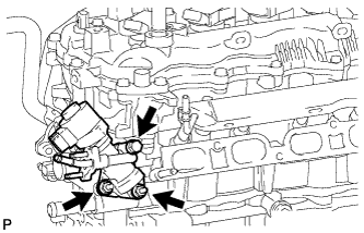
REMOVE EGR VALVE ASSEMBLY
-
Remove the bolt, 2 nuts and the EGR valve.
-
Remove the EGR valve gaskets.
-
-
REMOVE FUEL DELIVERY PIPE
-
Disconnect the 4 fuel injector assembly connectors.
-
Remove the 2 bolts and delivery pipe together with the 4 injectors.
Note
Do not drop the fuel injectors when removing the fuel delivery pipe.
-
-
REMOVE FUEL INJECTOR ASSEMBLY
-
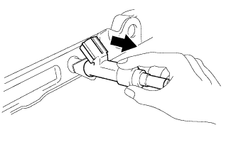
Pull the 4 fuel injector assemblies out of the fuel delivery pipe sub-assembly.
-
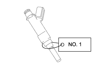
For reinstallation, attach a tag or label to each injector shaft.
Note
Prevent entry of foreign objects by covering the fuel injectors with plastic bags.
-
-
REMOVE NO. 1 DELIVERY PIPE SPACER
-
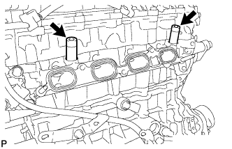
Remove the 2 No. 1 delivery pipe spacers from the cylinder head.
-
-
REMOVE INJECTOR VIBRATION INSULATOR
-
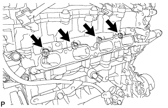
Remove the 4 injector vibration insulators.
-
-
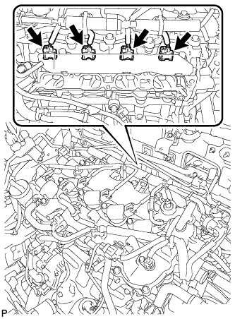
REMOVE NO. 1 IGNITION COIL
-
Remove the 4 bolts and remove the 4 No. 1 ignition coils.
-
-
REMOVE VENTILATION HOSE
-
Remove the ventilation hose from the cylinder head cover.
-
-
REMOVE NO. 2 VENTILATION HOSE
-
Remove the No. 2 ventilation hose from the cylinder head cover.
-
-
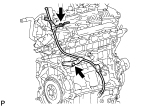
REMOVE NO. 1 WATER BY-PASS PIPE
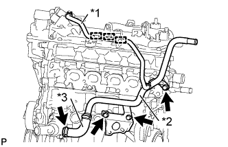
Text in Illustration *1 No. 2 Water By-Pass Hose *2 No. 1 Water By-Pass Pipe *3 Water By-Pass Hose
-
Disengage the No. 2 water by-pass hose from the 3 clamps.
-
Remove the 3 bolts.
-
Disconnect the water by-pass hose and remove the No. 1 water by-pass pipe.
-
-
REMOVE NO. 2 IDLE PULLEY ASSEMBLY WITH BRACKET (w/ Air Conditioning System)
-
Remove the 4 bolts and the No. 2 idle pulley assembly with bracket.
-
-
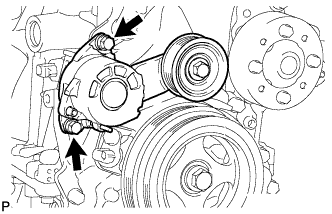
REMOVE V-RIBBED BELT TENSIONER ASSEMBLY
-
Remove the 2 bolts and the V-ribbed belt tensioner.
-
-
REMOVE V-RIBBED BELT TENSIONER ASSEMBLY (w/ No. 1 Engine Cover)

-
Remove the 2 bolts, V-ribbed belt tensioner and engine cover bracket.
-
-
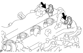
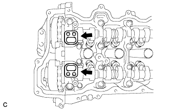
REMOVE NO. 1 CRANKSHAFT POSITION SENSOR
-
Remove the 2 bolts and the 2 No. 1 crankshaft position sensors.
-
-
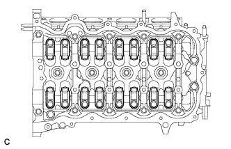
REMOVE CYLINDER HEAD COVER SUB-ASSEMBLY
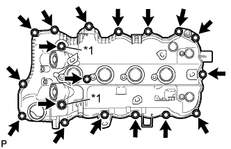
Text in Illustration *1 Seal Washer
-
Remove the 18 bolts, 2 seal washers and the cylinder head cover.
Note
Be careful not to drop any of the gaskets into the engine when removing the cylinder head cover because the gaskets may stick to the cylinder head cover.
-
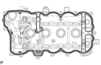
Remove the cylinder head cover gasket.
-
-
REMOVE CAMSHAFT BEARING CAP OIL HOLE GASKET
-
Remove the 2 camshaft bearing cap oil hole gaskets from the camshaft bearing cap.
-
-
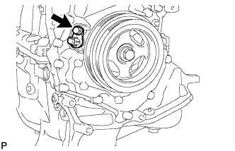
REMOVE CRANKSHAFT POSITION SENSOR
-
Remove the bolt and the crankshaft position sensor.
-
-
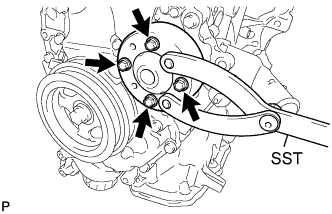
REMOVE WATER PUMP PULLEY
-
Using SST, remove the 4 bolts and water pump pulley.
- SST
- 09960-10010 ( 09962-01000, 09963-00600 )
-
-
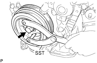
REMOVE CRANKSHAFT PULLEY
-
Using SST, remove the crankshaft pulley bolt.
- SST
- 09960-10010 ( 09962-01000, 09963-01000 )
-
Remove the crankshaft pulley from the crankshaft.
-
-
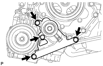
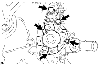
REMOVE TIMING CHAIN COVER SUB-ASSEMBLY
-
Remove the 5 bolts and the water pump, water pump gasket from the timing chain cover.
-
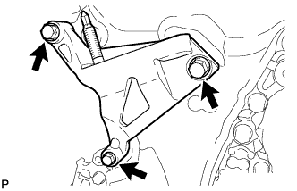
Remove the 3 bolts and the engine mounting bracket.
-
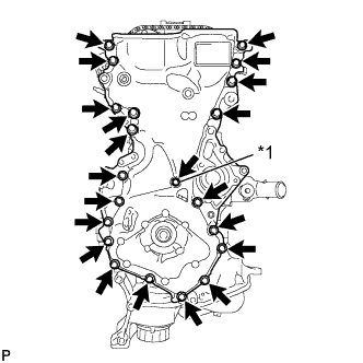
Text in Illustration *1 Seal Washer Remove the 21 bolts and seal washer.
-
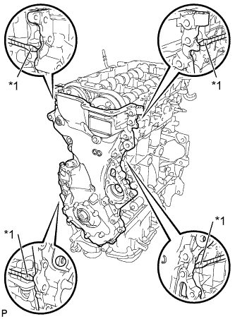
Text in Illustration *1 Protective Tape Using a screwdriver with its tip wrapped with protective tape, remove the timing chain cover by prying between the timing chain cover and cylinder head or cylinder block.
Note
Be careful not to damage the contact surfaces of the timing chain cover, cylinder block, and cylinder head.
-
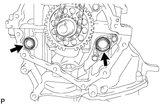
Remove the 2 O-rings.
-
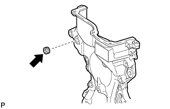
Using an 8 mm socket hexagon wrench, remove the plug.
-
-
REMOVE TIMING CHAIN COVER OIL SEAL
-
Text in Illustration *1 Protective Tape *2 Wooden Block Using a screwdriver with its tip wrapped with protective tape, remove the timing chain cover oil seal.
Note
Do not damage the surface of the oil seal press fit hole.
-
-
REMOVE NO. 1 CHAIN TENSIONER ASSEMBLY
-
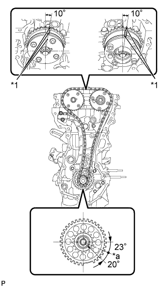
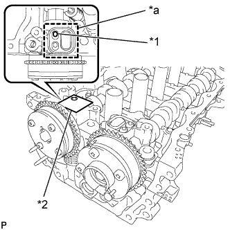
Set the camshaft timing gear, camshaft timing exhaust gear and crankshaft in the positions (20° ATDC) shown in the illustration.
Text in Illustration *1 Timing Mark *a TDC -
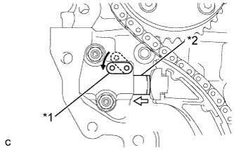
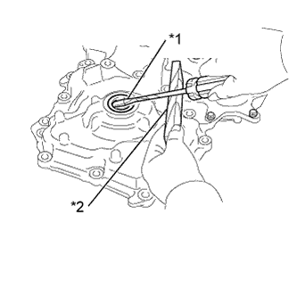
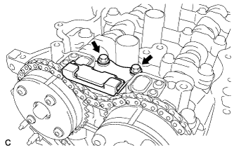
Text in Illustration *1 Stopper Plate *2 Plunger 
Push Push down on the stopper plate to release the lock and push in the plunger.
-
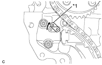
Text in Illustration *1 Stopper Plate Pull up the stopper plate with the plunger pushed to the end and lock the plunger.
-
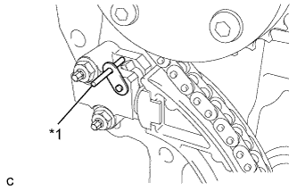
Text in Illustration *1 Bar Insert a 3 mm (0.118 in.) diameter bar into the hole in the stopper plate and lock the plunger.
-
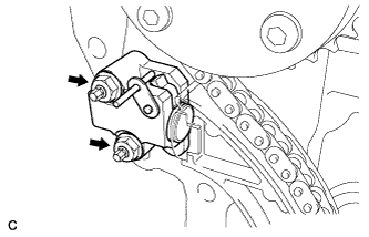
Remove the 2 nuts and the No. 1 chain tensioner.
-
Remove the gasket from the cylinder head.
-
-
REMOVE NO. 2 CHAIN VIBRATION DAMPER
-
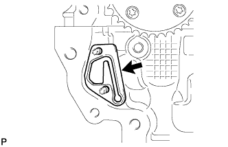
Remove the 2 bolts and the No. 2 chain vibration damper.
-
-
REMOVE TIMING CHAIN TENSION ARM
-
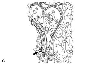
Remove the bolt and the timing chain tension arm.
-
-
REMOVE CHAIN SUB-ASSEMBLY
-
Remove the chain.
-
-
REMOVE TIMING CHAIN GUIDE
-
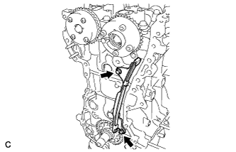
Remove the 2 bolts and the timing chain guide.
-
-
INSPECT CAMSHAFT TIMING GEAR ASSEMBLY
-
Inspect the lock of the camshaft timing gear.
-
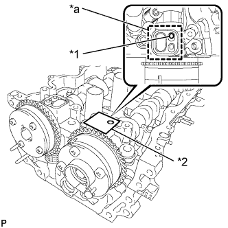
Text in Illustration *1 Prick a Hole *2 Adhesive Tape *a Adhesive Tape Sealing Area After cleaning and degrease the VVT oil hole on the intake side of the No. 1 camshaft bearing cap, completely seal the oil hole with adhesive tape or equivalent as shown in the illustration to prevent air from leaking.
Note
Be sure to seal the oil hole completely because air leaks due to insufficient sealing will prevent the lock pin from being released.
-
Prick a hole in the tape covering the oil hole as shown in the illustration (Procedure A).
-
Apply approximately 150 kPa (1.5 kgf/cm2, 22 psi) of air pressure to the hole pricked in procedure A to release the lock pin.
Note
-
If air leaks out, reattach adhesive tape.
-
Cover the oil hole with a piece of cloth when applying air pressure to prevent oil from spraying.
-
-
Forcibly turn the camshaft timing gear assembly in the advance direction (counterclockwise).
Tech Tips
Depending on the air pressure applied, the camshaft timing gear assembly may turn in the advance direction without assistance by hand.
-
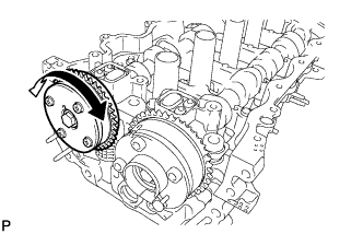
Turn the camshaft timing gear assembly within its movable range (26.5 to 28.5°) 2 or 3 times without turning it to the most retarded position. Make sure that the camshaft timing gear assembly turns smoothly.
-
Remove the adhesive tape from the No. 1 camshaft bearing cap.
-
-
INSPECT CAMSHAFT TIMING EXHAUST GEAR ASSEMBLY
-
Check the lock of the camshaft timing exhaust gear.
-
Text in Illustration *1 Prick a Hole *2 Adhesive Tape *a Adhesive Tape Sealing Area After cleaning and degrease the VVT oil hole on the exhaust side of the No. 1 camshaft bearing cap, completely seal the oil hole with adhesive tape or equivalent as shown in the illustration to prevent air from leaking.
Note
Be sure to seal the oil hole completely because air leaks due to insufficient sealing will prevent the lock pin from being released.
-
Prick a hole in the tape covering the oil hole as shown in the illustration (Procedure B).
-
Apply approximately 200 kPa (2.0 kgf/cm2, 28 psi) of air pressure to the hole pricked in procedure B to release the lock pin.
Note
-
If air leaks out, reattach adhesive tape.
-
Cover the oil hole with a piece of cloth when applying air pressure to prevent oil from spraying.
-
-
Using a screwdriver with its tip wrapped with tape, forcibly turn the camshaft timing exhaust gear in the retard direction (clockwise).
Note
-
Be sure to keep the camshaft timing exhaust gear in the retard direction using a screwdriver. If the gear is released, it will return to the most advanced position automatically due to force from the spring.
-
Do not damage the camshaft timing exhaust gear.
-
-
Using a screwdriver with its tip wrapped with tape, turn the camshaft timing exhaust gear within its movable range (19 to 21°) 2 or 3 times without turning it to the most advanced position. Make sure that the camshaft timing exhaust gear turns smoothly.
-
Remove the adhesive tape from the No. 1 camshaft bearing cap.
-
-
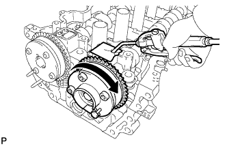
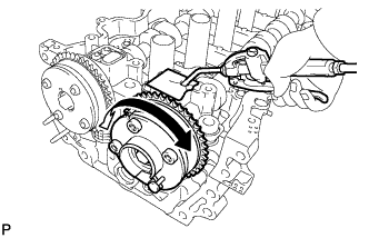
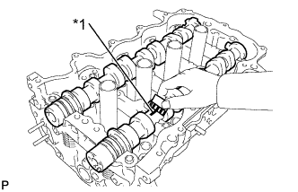
REMOVE CAMSHAFT TIMING GEAR ASSEMBLY
-
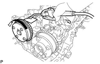
Text in Illustration *a Do Not Remove Remove the flange bolt while holding the hexagonal portion of the camshaft, and then remove the camshaft timing gear assembly.
Note
-
Before removing the camshaft timing gear, make sure that the lock pin has been released.
-
Be sure not to remove the other 4 bolts.
-
Keep the camshaft timing gear assembly horizontal while removing it from the camshaft.
-
-
-
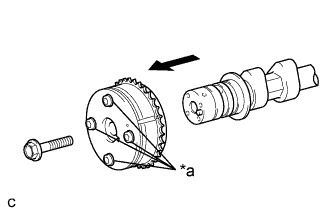
REMOVE CAMSHAFT TIMING EXHAUST GEAR ASSEMBLY
-
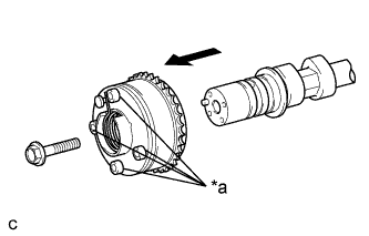
Text in Illustration *a Do Not Remove Remove the flange bolt while holding the hexagonal portion of the camshaft, and then remove the camshaft timing exhaust gear assembly.
Note
-
Be sure not to remove the other 4 bolts.
-
Keep the camshaft timing exhaust gear assembly horizontal while removing it from the camshaft.
-
-
-
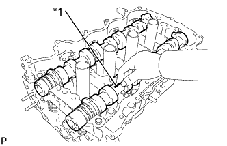
REMOVE CAMSHAFT BEARING CAP
-
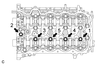
Uniformly loosen and remove the 5 bearing cap bolts in the sequence shown in the illustration.
-
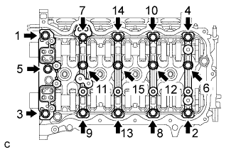
Uniformly loosen and remove the 15 bearing cap bolts in the sequence shown in the illustration.
Note
Uniformly loosen the bolts while keeping the camshaft level.
-
Remove the 5 bearing caps.
Tech Tips
Arrange the removed parts in the correct order.
-
-
REMOVE NO. 2 CAMSHAFT
-
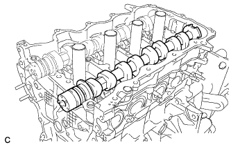
Remove the No. 2 camshaft.
-
-
REMOVE CAMSHAFT
-
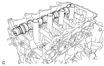
Remove the camshaft.
-
-
REMOVE NO. 1 VALVE ROCKER ARM SUB-ASSEMBLY
-
Remove the 16 valve rocker arms.
Tech Tips
Arrange the removed parts in the correct order.
-
-
REMOVE VALVE LASH ADJUSTER ASSEMBLY
-
Remove the 16 valve lash adjusters from the cylinder head.
Tech Tips
Arrange the removed parts in the correct order.
-
-
REMOVE CAMSHAFT HOUSING SUB-ASSEMBLY
-
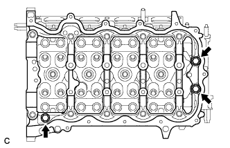
Remove the 3 bolts.
-
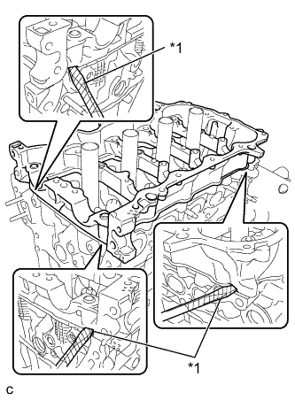
Text in Illustration *1 Protective Tape Using a screwdriver with its tip wrapped with protective tape, remove the camshaft housing by prying between the cylinder head and camshaft housing.
Note
Be careful not to damage the contact surfaces of the cylinder head and camshaft housing.
-
-
INSPECT CAMSHAFT
-
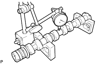
Inspect the camshaft for runout.
-
Place the camshaft on V-blocks.
-
Using a dial indicator, measure the circle runout at the center journal.
Maximum circle runout 0.04 mm (0.00157 in.) If the circle runout is greater than the maximum, replace the camshaft.
-
-
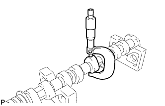
Inspect the cam lobes.
-
Using a micrometer, measure the cam lobe height.
Standard cam lobe height 41.699 to 41.7989 mm (1.6417 to 1.6456 in.) Minimum cam lobe height 41.549 mm (1.6358 in.) If the cam lobe height is less than the minimum, replace the camshaft.
-
-
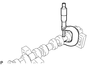
Inspect the camshaft journals.
-
Using a micrometer, measure the journal diameter.
Standard Journal Diameter Journal Position Specified Condition No. 1 34.454 to 34.470 mm (1.3565 to 1.3571 in.) Other 22.954 to 22.970 mm (0.9037 to 0.9043 in.) If the journal diameter is not as specified, check the camshaft oil clearance.
-
-
-
INSPECT NO. 2 CAMSHAFT
-
Inspect the No. 2 camshaft for runout.
-
Place the No. 2 camshaft on V-blocks.
-
Using a dial indicator, measure the circle runout at the center journal.
Maximum circle runout 0.04 mm (0.00157 in.) If the circle runout is greater than the maximum, replace the No. 2 camshaft.
-
-
Inspect the cam lobes.
-
Using a micrometer, measure the cam lobe height.
Standard cam lobe height 41.000 to 41.100 mm (1.6142 to 1.6181 in.) Minimum cam lobe height 40.85 mm (1.6083 in.) If the cam lobe height is less than the minimum, replace the No. 2 camshaft.
-
-
Inspect the camshaft journals.
-
Using a micrometer, measure the journal diameter.
Standard Journal Diameter Journal Position Specified Condition No. 1 34.454 to 34.470 mm (1.3565 to 1.3571 in.) Other 22.954 to 22.970 mm (0.9037 to 0.9043 in.) If the journal diameter is not as specified, check the camshaft oil clearance.
-
-
-
INSPECT CAMSHAFT THRUST CLEARANCE
-
Install the camshaft Click here.
-
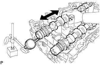
Install the No. 2 camshaft Click here.
-
Using a dial indicator, measure the thrust clearance while moving the camshaft back and forth.
Standard Thrust Clearance Item Specified Condition Intake 0.06 to 0.2 mm (0.00236 to 0.00787 in.) Exhaust 0.06 to 0.2 mm (0.00236 to 0.00787 in.) Maximum Thrust Clearance Item Specified Condition Intake 0.215 mm (0.00846 in.) Exhaust 0.215 mm (0.00846 in.) If the thrust clearance is greater than the maximum, replace the camshaft housing. If the thrust surface is damaged, replace the camshaft.
-
-
INSPECT CAMSHAFT OIL CLEARANCE
-
Text in Illustration *1 Plastigage Clean the bearing caps and camshaft journals.
-
Place the camshafts on the camshaft housing.
-
Lay a strip of Plastigage across each of the camshaft journals.
-
Install the camshaft bearing cap Click here.
Note
Do not turn the camshaft.
-
Remove the camshaft bearing cap Click here.
-
Text in Illustration *1 Plastigage Measure the Plastigage at its widest point.
Standard Oil Clearance Item Specified Condition No. 1 camshaft journal 0.030 to 0.067 mm (0.00118 to 0.00264 in.) Other camshaft journals 0.030 to 0.067 mm (0.00118 to 0.00264 in.) Maximum Oil Clearance Item Specified Condition No. 1 camshaft journal 0.08 mm (0.00315 in.) Other camshaft journals 0.08 mm (0.00315 in.) Note
Completely remove the Plastigage after the inspection.
If the oil clearance is greater than the maximum, replace the camshaft. If necessary, replace the camshaft housing.
-
-
INSPECT NO. 1 VALVE ROCKER ARM SUB-ASSEMBLY
-
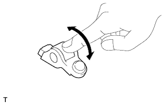
Turn the roller by hand to check that it turns smoothly.
Tech Tips
If the roller does not turn smoothly, replace the valve rocker arm.
-
-
INSPECT VALVE LASH ADJUSTER ASSEMBLY
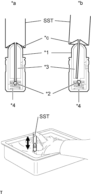
Text in Illustration *1 Plunger *2 Check Ball *3 Low Pressure Chamber *4 High Pressure Chamber *a Correct *b Incorrect *c Taper Part Note
-
Keep the lash adjuster free of dirt and foreign matter.
-
Only use clean engine oil.
-
Place the lash adjuster into a container filled with engine oil.
-
Insert the tip of SST into the lash adjuster plunger and use the tip to press down on the check ball inside the plunger.
- SST
- 09276-75010
-
Squeeze SST and the lash adjuster together to move the plunger up and down 5 to 6 times.
-
Check the movement of the plunger and bleed it.
OK Plunger moves up and down. Note
When bleeding the high-pressure chamber, make sure that the tip of SST is actually pressing the check ball as shown in the illustration. If the check ball is not pressed, the high-pressure chamber will not be bled.
-
After bleeding, remove SST. Then, try to quickly and firmly press the plunger by hand.
OK Plunger is very difficult to move. If the result is not as specified, replace the lash adjuster.
-