SFI SYSTEM, Diagnostic DTC:P0105, P0107, P0108

| DTC Code | DTC Name |
|---|---|
| P0105 | Manifold Absolute Pressure / Barometric Pressure Circuit |
| P0107 | Manifold Absolute Pressure / Barometric Pressure Circuit Low Input |
| P0108 | Manifold Absolute Pressure / Barometric Pressure Circuit High Input |
DESCRIPTION
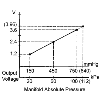
By a built-in sensor unit, the manifold absolute pressure detects the intake manifold pressure as a voltage.
| DTC No. | DTC Detection Condition | Trouble Area |
|---|---|---|
| P0105 | The output voltage from the vacuum sensor remains 0.5 V or less for 0.5 seconds or more (1 trip detection logic). |
|
| The output voltage from the vacuum sensor remains 4.5 V or more for 0.5 seconds or more (1 trip detection logic). |
||
| P0107 | The output voltage from the vacuum sensor remains 0.5 V or less for 0.5 seconds or more (1 trip detection logic). |
|
| P0108 | The output voltage from the vacuum sensor remains 4.5 V or more for 0.5 seconds or more (1 trip detection logic). |
|
Tech Tips
-
DTC P0105, P0107 and P0108 are detected when the ignition switch is ON for approximately 2 seconds.
-
When DTC P0105, P0107 or P0108 is detected, check the manifold absolute pressure by entering the following menus: Powertrain / Engine and ECT / Data List / MAP.
| Manifold Absolute Pressure | Malfunction |
|---|---|
| Approximately 0 kPa (0 mmHg) |
|
| 130 kPa (975 mmHg) or more |
|
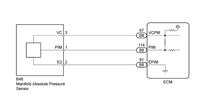
WIRING DIAGRAM
INSPECTION PROCEDURE
Tech Tips
Read freeze frame data using the intelligent tester. The ECM records vehicle and driving condition information as freeze frame data the moment a DTC is stored. When troubleshooting, freeze frame data can help determine if the vehicle was moving or stationary, if the engine was warmed up or not, if the air-fuel ratio was lean or rich, and other data from the time the malfunction occurred.
PROCEDURE
-
READ VALUE USING INTELLIGENT TESTER (MAP)
-
Connect the intelligent tester to the DLC3.
-
Turn the ignition switch to ON.
-
Turn the tester on.
-
Enter the following menus: Powertrain / Engine and ECT / Data List / MAP.
-
Read the MAP value.
OK Same value as the actual atmospheric pressure Tech Tips
-
Standard atmospheric pressure is 101 kPa (758 mmHg). For every 100 m (328 ft.) increase in altitude, pressure drops by 1 kPa (7.50 mmHg). Varies by weather (high atmospheric pressure, low atmospheric pressure).
-
Also, check "Atmosphere Pressure" in the Data List.
-
NG 
CHECK TERMINAL VOLTAGE (MANIFOLD ABSOLUTE PRESSURE SENSOR) Click here
OK 
CHECK FOR INTERMITTENT PROBLEMS Click here
-
-
CHECK TERMINAL VOLTAGE (MANIFOLD ABSOLUTE PRESSURE SENSOR)
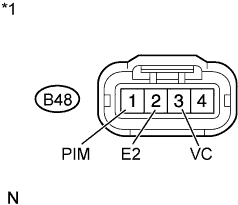
Text in Illustration *1 Front view of wire harness connector:
(to Manifold Absolute Pressure Sensor)
-
Disconnect the manifold absolute pressure sensor connector.
-
Turn the ignition switch to ON.
-
Measure the voltage between the terminals of the manifold absolute pressure sensor connector.
Standard Voltage Tester Connection Switch Condition Specified Condition B48-3 (VC) - B48-2 (E2) Ignition switch ON 4.5 to 5.5 V B48-1 (PIM) - B48-2 (E2) Ignition switch ON 4.0 to 5.0 V -
Reconnect the manifold absolute pressure sensor connector.
NG
CHECK HARNESS AND CONNECTOR (MANIFOLD ABSOLUTE PRESSURE SENSOR - ECM) Click here
OK 
-
-
REPLACE MANIFOLD ABSOLUTE PRESSURE SENSOR
-
Replace the manifold absolute pressure sensor Click here.
NEXT
-
-
CHECK WHETHER DTC OUTPUT RECURS (P0105, P0107 OR P0108)
-
Connect the intelligent tester to the DLC3.
-
Turn the ignition switch to ON and turn the tester on.
-
Clear the DTC Click here.
-
Turn the ignition switch off.
-
Turn the ignition switch to ON and wait for 2 seconds.
-
Enter the following menus: Powertrain / Engine and ECT / DTC.
-
Read DTCs.
OK No DTC output.
NG 
REPLACE ECM Click here
OK
END
-
-
CHECK HARNESS AND CONNECTOR (MANIFOLD ABSOLUTE PRESSURE SENSOR - ECM)
-
Disconnect the manifold absolute pressure sensor connector.
-
Disconnect the ECM connector.
-
Measure the resistance according to the value(s) in the table below.
Standard Resistance (Check for Open) Tester Connection Condition Specified Condition B48-3 (VC) - B8-67 (VCPM) Always Below 1 Ω B48-2 (E2) - B8-91 (EPIM) Always Below 1 Ω B48-1 (PIM) - B8-114 (PIM) Always Below 1 Ω Standard Resistance (Check for Short) Tester Connection Condition Specified Condition B48-3 (VC) or B8-67 (VCPM) - Body ground Always 10 kΩ or higher B48-2 (E2) or B8-91 (EPIM) - Body ground Always 10 kΩ or higher B48-1 (PIM) or B8-114 (PIM) - Body ground Always 10 kΩ or higher -
Reconnect the manifold absolute pressure sensor connector.
-
Reconnect the ECM connector.
NG
REPAIR OR REPLACE HARNESS OR CONNECTOR
OK
REPLACE ECM Click here
-