SFI SYSTEM Active Control Engine Mount System
DESCRIPTION
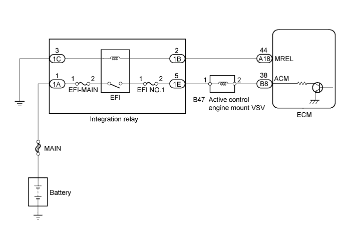
The Active Control Engine Mount (ACM) system decreases engine vibration at low engine speed using a active control engine mount VSV. The VSV is controlled by a pulse signal transmitted to the VSV from the ECM. The frequency of this pulse signal is matched to the engine speed to decrease engine vibration.
WIRING DIAGRAM
INSPECTION PROCEDURE
Note
Inspect the fuses for circuits related to this system before performing the following inspection procedure.
PROCEDURE
-
INSPECT VACUUM HOSE SUB-ASSEMBLY
-
Inspect if the vacuum hose is damaged, loose, disconnected, or blocked.
OK Vacuum hose is connected correctly and is not damaged.
NG 
REPLACE VACUUM HOSE SUB-ASSEMBLY
OK 
-
-
INSPECT ACTIVE CONTROL ENGINE MOUNT VSV
-
Inspect the active control engine mount VSV Click here.
NG
REPLACE ACTIVE CONTROL ENGINE MOUNT VSV Click here
OK
-
-
CHECK HARNESS AND CONNECTOR (ACTIVE CONTROL ENGINE MOUNT VSV - ECM - INTEGRATION RELAY)
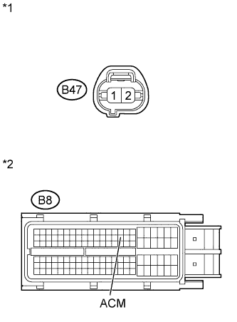
Text in Illustration *1 Front view of wire harness connector:
(to active control engine mount VSV)
*2 Front view of wire harness connector:
(to ECM)
-
Disconnect the active control engine mount VSV connector.
-
Disconnect the ECM connector.
-
Measure the resistance according to the value(s) in the table below.
Standard Resistance (Check for Open) Tester Connection Condition Specified Condition B47-2 - B8-38 (ACM) Always Below 1 Ω Standard Resistance (Check for Short) Tester Connection Condition Specified Condition B47-2 or B8-38 (ACM) - Body ground Always 10 kΩ or higher -
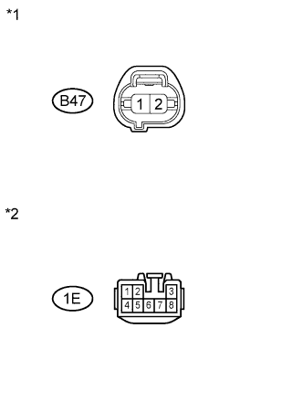
Text in Illustration *1 Front view of wire harness connector:
(to active control engine mount VSV)
*2 Front view of wire harness connector:
(to Integration relay)
Remove the integration relay from the engine room relay block.
-
Disconnect the active control engine mount VSV connector.
-
Measure the resistance according to the value(s) in the table below.
Standard Resistance Tester Connection Condition Specified Condition B47-1 - 1E-5 Always Below 1 Ω -
Reconnect the active control engine mount VSV connector.
-
Reconnect the ECM connector.
-
Install the integration relay.
NG
REPAIR OR REPLACE HARNESS OR CONNECTOR
OK
-
-
INSPECT ENGINE MOUNTING INSULATOR FRONT
-
Inspect the engine mounting insulator front Click here.
NG
REPLACE ENGINE MOUNTING INSULATOR FRONT Click here
OK 
REPLACE ECM Click here
-