SFI SYSTEM, Diagnostic DTC:P0560

| DTC Code | DTC Name |
|---|---|
| P0560 | System Voltage |
DESCRIPTION
The battery supplies electricity to the ECM even when the ignition switch is off. This power allows the ECM to store data such as DTC history, freeze frame data and fuel trim values. If the battery voltage falls below a minimum level, the memory is cleared and the ECM determines that there is a malfunction in the power supply circuit. When the engine is next started, the ECM will illuminate the MIL and set the DTC.
| DTC No. | DTC Detection Condition | Trouble Area |
|---|---|---|
| P0560 | Open in ECM back-up power source circuit (1-trip detection logic) |
|
Tech Tips
If DTC P0560 is set, the ECM does not store other DTCs or the data stored in the ECM is partly cleared.
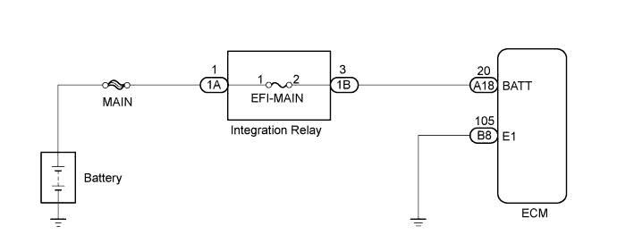
WIRING DIAGRAM
INSPECTION PROCEDURE
Note
Inspect the fuses for circuits related to this system before performing the following inspection procedure.
Tech Tips
Read freeze frame data using an intelligent tester. The ECM records vehicle and driving condition information as freeze frame data the moment a DTC is stored. When troubleshooting, freeze frame data can help determine if the vehicle was moving or stationary, if the engine was warmed up or not, if the air-fuel ratio was lean or rich, and other data from the time the malfunction occurred.
PROCEDURE
-
CHECK HARNESS AND CONNECTOR (INTEGRATION RELAY - ECM)
-
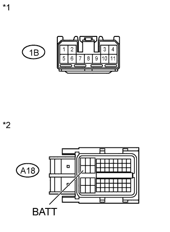
Text in Illustration *1 Front view of wire harness connector:
(to Integration Relay)
*2 Front view of wire harness connector:
(to ECM)
Disconnect the ECM connector.
-
Remove the integration relay from engine room relay block.
-
Measure the resistance according to the value(s) in the table below.
Standard Resistance (Check for Open) Tester Connection Condition Specified Condition 1B-3 - A18-20 (BATT) Always Below 1 Ω Standard Resistance (Check for Short) Tester Connection Condition Specified Condition 1B-3 or A18-20 (BATT) - Body ground Always 10 kΩ or higher -
Reconnect the ECM connector.
-
Reinstall the integration relay.
NG 
REPAIR OR REPLACE HARNESS OR CONNECTOR
OK 
-
-
CHECK HARNESS AND CONNECTOR (INTEGRATION RELAY - BATTERY)
-
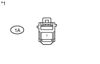
Text in Illustration *1 Front view of wire harness connector:
(to Integration Relay)
Remove the integration relay from engine room relay block.
-
Disconnect the negative battery terminal.
-
Disconnect the positive battery terminal.
-
Measure the resistance according to the value(s) in the table below.
Standard Resistance (Check for Open) Tester Connection Condition Specified Condition 1A-1 - Battery positive terminal Always Below 1 Ω Standard Resistance (Check for Short) Tester Connection Condition Specified Condition 1A-1 or Battery positive terminal - Body ground Always 10 kΩ or higher -
Reconnect the positive battery terminal.
-
Reconnect the negative battery terminal.
NG
REPAIR OR REPLACE HARNESS OR CONNECTOR
OK
-
-
INSPECT INTEGRATION NO.1 RELAY
-
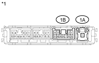
Text in Illustration *1 Front view of wire harness connector:
(to Integration Relay)
Remove the integration relay from engine room relay block.
-
Measure the voltage according to the value(s) in the table below.
Standard Resistance (Check for Open) Tester Connection Condition Specified Condition 1A-1 - 1B-3 Always Below 1 Ω -
Reinstall the integration relay.
NG
REPLACE INTEGRATION NO.1 RELAY Click here
OK
-
-
INSPECT BATTERY
-
Measure the voltage according to the value(s) in the table below.
Standard Voltage Tester Connection Condition Specified Condition Battery terminals 20°C (68°F) 12.5 to 12.9 V
NG
REPLACE BATTERY
OK
-
-
CHECK BATTERY TERMINAL
-
Check that the battery terminals are not loose or corroded.
OK Battery terminals are not loose or corroded.
NG
REPAIR OR REPLACE BATTERY TERMINAL
OK
-
-
CHECK WHETHER DTC OUTPUT RECURS (DTC P0560)
-
Connect an intelligent tester to the DLC3.
-
Turn the ignition switch to ON.
-
Turn the tester on.
-
Enter the following menus: Powertrain / Engine and ECT / DTC / Clear.
-
Clear DTCs.
-
Turn the ignition switch off and turn the tester off.
-
Start the engine and turn the tester on.
-
Enter the following menus: Powertrain / Engine and ECT/ DTC.
-
Read DTCs.
Result Result Proceed to P0560 A No output B
B
CHECK FOR INTERMITTENT PROBLEMS Click here
A 
REPLACE ECM Click here
-