SFI SYSTEM, Diagnostic DTC:P0037, P0038

| DTC Code | DTC Name |
|---|---|
| P0037 | Oxygen Sensor Heater Control Circuit Low (Bank 1 Sensor 2) |
| P0038 | Oxygen Sensor Heater Control Circuit High (Bank 1 Sensor 2) |
DESCRIPTION
-
Refer to DTC P0136 Click here.
Tech Tips
-
Sensor 2 refers to the sensor mounted behind the three-way catalytic converter and located far from the engine assembly.
-
When any of these DTCs are set, the ECM enters fail-safe mode. The ECM turns off the heated oxygen sensor heater in fail-safe mode. Fail-safe mode continues until the ignition switch is turned off.
-
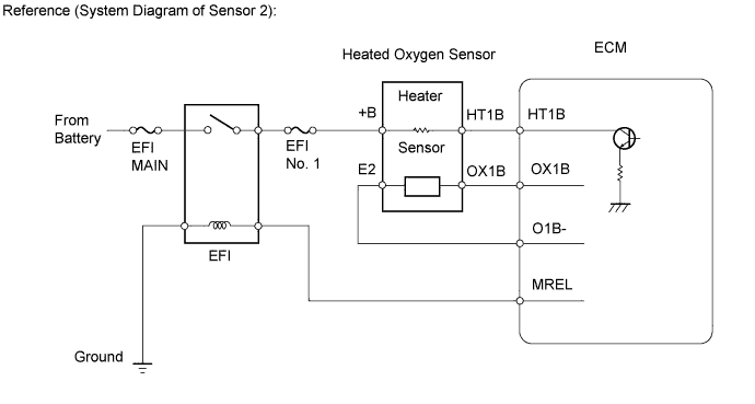
The ECM provides a pulse width modulated signal to the control circuit to adjust the current through the heater. The heated oxygen sensor heater circuit uses a relay on the +B side of the circuit.
| DTC No. | DTC Detection Condition | Trouble Area |
|---|---|---|
| P0037 | Heated oxygen sensor heater current less than 0.3 A (1-trip detection logic) |
|
| P0038 | Heated oxygen sensor heater current more than 2 A (1-trip detection logic) |
|
WIRING DIAGRAM
Refer to DTC P0136 Click here.
INSPECTION PROCEDURE
Note
Inspect the fuses for circuits related to this system before performing the following inspection procedure.
Tech Tips
Read freeze frame data using an intelligent tester. The ECM records vehicle and driving condition information as freeze frame data the moment a DTC is stored. When troubleshooting, freeze frame data can help determine if the vehicle was moving or stationary, if the engine was warmed up or not, if the air fuel ratio was lean or rich, and other data from the time the malfunction occurred.
PROCEDURE
-
INSPECT HEATED OXYGEN SENSOR (HEATER RESISTANCE)
-
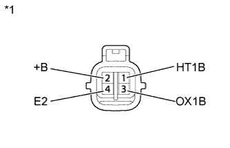
Text in Illustration *1 Component without harness connected:
(Heated Oxygen Sensor)
Disconnect the heated oxygen sensor connector.
-
Measure the resistance according to the value(s) in the table below.
Standard Resistance Tester Connection Condition Specified Condition 1 (HT1B) - 2 (+B) 20°C (68°F) 11 to 16 Ω 1 (HT1B) - 4 (E2) Always 10 kΩ or higher -
Reconnect the heated oxygen sensor connector.
NG 
REPLACE HEATED OXYGEN SENSOR Click here
OK 
-
-
CHECK TERMINAL VOLTAGE (POWER SOURCE)
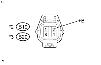
Text in Illustration *1 Front view of wire harness connector:
(to Heated Oxygen Sensor)
*2 for CVT *3 for Manual Transaxle
-
Disconnect the heated oxygen sensor connector.
-
Turn the ignition switch to ON.
-
Measure the voltage according to the value(s) in the table below.
Standard Voltage Tester Connection Switch Condition Specified Condition B19-2 (+B)*2 - Body ground Ignition switch ON 11 to 14 V B20-2 (+B)*3 - Body ground Ignition switch ON 11 to 14 V -
Reconnect the heated oxygen sensor connector.
NG 
CHECK HARNESS AND CONNECTOR (HEATED OXYGEN SENSOR - INTEGRATION RELAY) Click here
OK
-
-
CHECK HARNESS AND CONNECTOR (HEATED OXYGEN SENSOR - ECM)
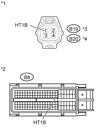
Text in Illustration *1 Front view of wire harness connector:
(to Heated Oxygen Sensor)
*2 Front view of wire harness connector:
(to ECM)
*3 for CVT *4 for Manual Transaxle
-
Disconnect the heated oxygen sensor connector.
-
Disconnect the ECM connector.
-
Measure the resistance according to the value(s) in the table below.
Standard Resistance (Check for Open) Tester Connection Condition Specified Condition B19-1 (HT1B)*3 - B8-63 (HT1B) Always Below 1 Ω B20-1 (HT1B)*4 - B8-63 (HT1B) Always Below 1 Ω Standard Resistance (Check for Short) Tester Connection Condition Specified Condition B19-1 (HT1B)*3 or B8-63 (HT1B) - Body ground Always 10 kΩ or higher B20-1 (HT1B)*4 or B8-63 (HT1B) - Body ground Always 10 kΩ or higher -
Reconnect the heated oxygen sensor connector.
-
Reconnect the ECM connector.
NG
REPAIR OR REPLACE HARNESS OR CONNECTOR
OK 
REPLACE ECM Click here
-
-
CHECK HARNESS AND CONNECTOR (HEATED OXYGEN SENSOR - INTEGRATION RELAY)
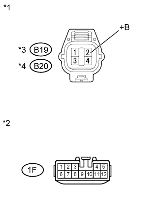
Text in Illustration *1 Front view of wire harness connector:
(to Heated Oxygen Sensor)
*2 Front view of wire harness connector:
(to Integration Relay)
*3 for CVT *4 for Manual Transaxle
-
Disconnect the heated oxygen sensor connector.
-
Remove the integration relay (EFI relay) from the engine room relay block and junction block.
-
Measure the resistance according to the value(s) in the table below.
Standard Resistance (Check for Open) Tester Connection Condition Specified Condition B19-2 (+B)*3 - 1F-12 Always Below 1 Ω B20-2 (+B)*4 - 1F-12 Always Below 1 Ω Standard Resistance (Check for Short) Tester Connection Condition Specified Condition B19-2 (+B)*3 or 1F-12 - Body ground Always 10 kΩ or higher B20-2 (+B)*4 or 1F-12 - Body ground Always 10 kΩ or higher -
Reconnect the heated oxygen sensor connector.
-
Reinstall the integration relay.
NG
REPAIR OR REPLACE HARNESS OR CONNECTOR
OK
REPAIR OR REPLACE ECM POWER SOURCE CIRCUIT Click here
-