SFI SYSTEM, Diagnostic DTC:P0010

| DTC Code | DTC Name |
|---|---|
| P0010 | Camshaft Position "A" Actuator Circuit (Bank 1) |
DESCRIPTION
Tech Tips
-
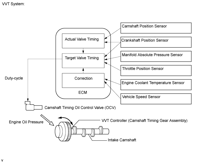
This DTC relates to the Camshaft Timing Oil Control Valve (OCV).
The Variable Valve Timing (VVT) system includes the ECM, OCV and VVT controller. The ECM sends a target duty-cycle control signal to the OCV. This control signal regulates the oil pressure applied to the VVT controller. Camshaft timing control is performed according to engine operating conditions such as the intake air volume, throttle valve position and engine coolant temperature. The ECM controls the OCV, based on the signals transmitted by several sensors. The VVT controller regulates the intake camshaft angle using oil pressure through the OCV. As a result, the relative positions of the camshaft and crankshaft are optimized, the engine torque and fuel economy improve, and the exhaust emissions decrease under overall driving conditions. The ECM detects the actual intake valve timing using signals from the camshaft and crankshaft position sensors, and performs feedback control. This is how the target intake valve timing is verified by the ECM.
| DTC No. | DTC Detection Condition | Trouble Area |
|---|---|---|
| P0010 | Open or short in Camshaft Timing Oil Control Valve (OCV) circuit (1-trip detection logic) |
|
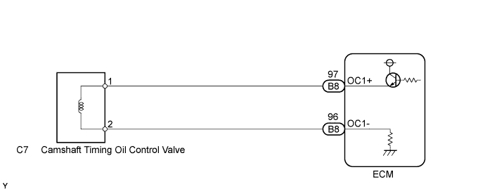
WIRING DIAGRAM
INSPECTION PROCEDURE
Tech Tips
Read freeze frame data using an intelligent tester. The ECM records vehicle and driving condition information as freeze frame data the moment a DTC is stored. When troubleshooting, freeze frame data can help determine if the vehicle was moving or stationary, if the engine was warmed up or not, if the air-fuel ratio was lean or rich, and other data from the time the malfunction occurred.
PROCEDURE
-
CHECK WHETHER DTC OUTPUT RECURS (DTC P0010)
-
Connect an intelligent tester to the DLC3.
-
Turn the ignition switch to ON.
-
Turn the tester on.
-
Enter the following menus: Powertrain / Engine and ECT / DTC / Clear.
-
Clear DTCs.
-
Start the engine and warm it up.
-
Enter the following menus: Powertrain / Engine and ECT / DTC.
-
Read DTCs.
Result Result Proceed to P0010 A No output B
B 
CHECK FOR INTERMITTENT PROBLEMS Click here
A 
-
-
INSPECT CAMSHAFT TIMING OIL CONTROL VALVE ASSEMBLY
-
Remove the OCV.
-
Measure the resistance according to the value(s) in the table below.
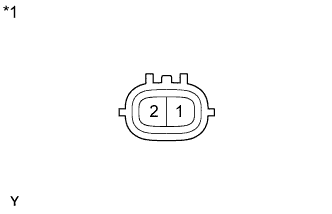
Standard Resistance Tester Connection Condition Specified Condition 1 - 2 20°C (68°F) 6.9 to 7.9 Ω Text in Illustration *1 Component without harness connected:
(OCV)
-
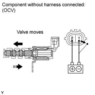
Apply battery voltage to terminals of the OCV. Check the valve operation.
OK Valve moves quickly. -
Reinstall the OCV.
NG
REPLACE CAMSHAFT TIMING OIL CONTROL VALVE ASSEMBLY Click here
OK
-
-
CHECK HARNESS AND CONNECTOR (OCV - ECM)
-
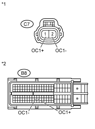
Text in Illustration *1 Front view of wire harness connector:
(to OCV)
*2 Front view of wire harness connector:
(to ECM)
Disconnect the OCV connector.
-
Disconnect the ECM connector.
-
Measure the resistance according to the value(s) in the table below.
Standard Resistance (Check for Open) Tester Connection Condition Specified Condition C7-1 (OC1+) - B8-97 (OC1+) Always Below 1 Ω C7-2 (OC1-) - B8-96 (OC1-) Always Below 1 Ω Standard Resistance (Check for Short) Tester Connection Condition Specified Condition C7-1 (OC1+) or B8-97 (OC1+) - Body ground Always 10 kΩ or higher C7-2 (OC1-) or B8-96 (OC1-) - Body ground Always 10 kΩ or higher -
Reconnect the OCV connector.
-
Reconnect the ECM connector.
NG
REPAIR OR REPLACE HARNESS OR CONNECTOR
OK 
REPLACE ECM Click here
-