SFI SYSTEM, Diagnostic DTC:P0724

| DTC Code | DTC Name |
|---|---|
| P0724 | Brake Switch "B" Circuit High |
DESCRIPTION
The purpose of this circuit is to prevent the engine from stalling while driving in the lock-up condition when the brakes are suddenly applied.
When the brake pedal is depressed, this switch sends a signal to the ECM. Then the ECM cancels the operation of the lock-up clutch while braking is in progress.
| DTC No. | DTC Detection Condition | Trouble Area |
|---|---|---|
| P0724 | Stop light switch remains ON even when vehicle is driven in GO (30 km/h (18.63 mph) or more) and STOP (less than 3 km/h (1.86 mph)) pattern 5 times (2-trip detection logic) |
|
WIRING DIAGRAM
Refer to DTC P0504 Click here.
INSPECTION PROCEDURE
Tech Tips
-
The following procedure is based on the premise that the stop lights are functioning normally. If the stop lights are not functioning, proceed to Stop Light Circuit Click here.
-
Read freeze frame data using the intelligent tester. The ECM records vehicle and driving condition information as freeze frame data the moment a DTC is stored. When troubleshooting, freeze frame data can help determine if the vehicle was moving or stationary, if the engine was warmed up or not, if the air-fuel ratio was lean or rich, and other data from the time the malfunction occurred.
PROCEDURE
-
READ VALUE USING INTELLIGENT TESTER (STOP LIGHT SWITCH ASSEMBLY)
-
Connect an intelligent tester to the DLC3.
-
Turn the ignition switch to ON.
-
Turn the tester on.
-
Enter the following menus: Powertrain / Engine and ECT / Data List / Stop Light Switch.
-
Read the value displayed on the tester when the brake pedal is depressed and released.
OK Brake Pedal Display Released OFF Depressed ON
NG 
INSPECT STOP LIGHT SWITCH ASSEMBLY Click here
OK 
CHECK FOR INTERMITTENT PROBLEMS Click here
-
-
INSPECT STOP LIGHT SWITCH ASSEMBLY
-
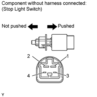
Remove the stop light switch assembly.
-
Measure the resistance according to the value(s) in the table below.
Standard Resistance Tester Connection Switch Condition Specified Condition 1 - 2 Switch pin not pushed Below 1 Ω Switch pin pushed 10 kΩ or higher 3 - 4 Switch pin not pushed 10 kΩ or higher Switch pin pushed Below 1 Ω -
Reinstall the stop light switch assembly.
NG 
REPLACE STOP LIGHT SWITCH ASSEMBLY
OK 
-
-
CHECK HARNESS AND CONNECTOR (ECM - STOP LIGHT SWITCH ASSEMBLY)
-
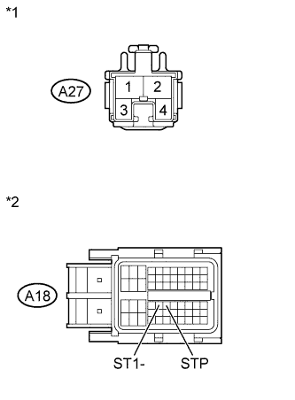
Text in Illustration *1 Front view of wire harness connector:
(to Stop Light Switch Assembly)
*2 Front view of wire harness connector:
(to ECM)
Disconnect the stop light switch assembly connector.
-
Disconnect the ECM connector.
-
Measure the resistance according to the value(s) in the table below.
Standard Resistance (Check for Open) Tester Connection Condition Specified Condition A18-36 (STP) - A27-1 Always Below 1 Ω A18-35 (ST-) - A27-4 Always Below 1 Ω Standard Resistance (Check for Short) Tester Connection Condition Specified Condition A18-36 (STP) or A27-1 - Body ground Always 10 kΩ or higher A18-35 (ST-) or A27-4 - Body ground Always 10 kΩ or higher -
Reconnect the ECM connector.
-
Reconnect the stop light switch assembly connector.
NG
REPAIR OR REPLACE HARNESS OR CONNECTOR
OK
REPLACE ECM Click here
-