HOOD LOCK CONTROL CABLE ASSEMBLY INSTALLATION

Tech Tips
-
Use the same procedure for LHD and RHD vehicles.
-
The procedure listed below is for LHD vehicles.
-
A bolt without a torque specification is shown in the standard bolt chart Click here.
-
INSTALL HOOD LOCK CONTROL CABLE ASSEMBLY (for LHD)
-
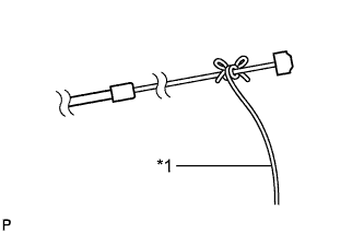
Text in Illustration *1 String Tie the string passed through the engine compartment to the end of the hood lock control cable assembly as shown in the illustration.
-
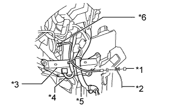
Pull the string until the hood lock control cable grommet contacts the dash panel, and then connect the clamps shown in the illustration to install the cable.
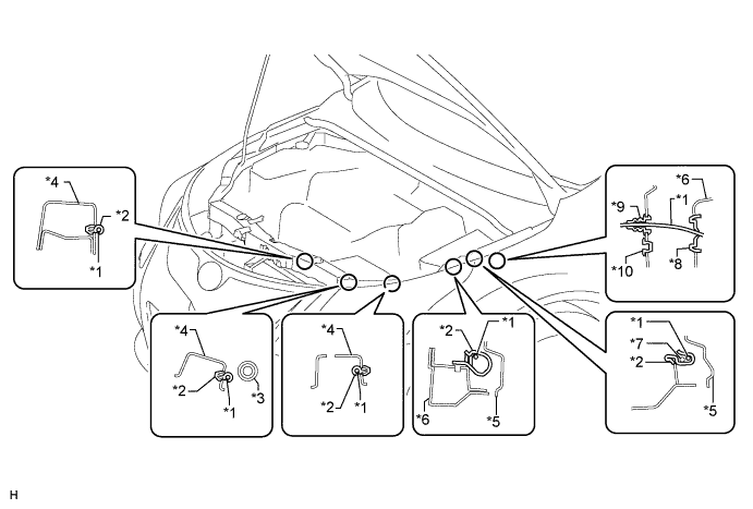
Text in Illustration *1 Hood Lock Control Cable *6 Apron *2 Clamp *7 w/ Rear Wiper:
Rear Washer Hose
*3 Bypass Hose *8 Grommet *4 Radiator Support Side *9 Hood Lock Control Cable Grommet *5 Fender Liner *10 Plug Hole -
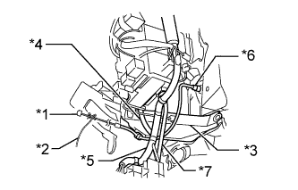
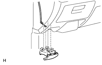
Text in Illustration *1 Hood Lock Control Cable *2 String *3 Dash to Frame Brace *4 Engine Room Main Wire *5 Instrument Panel Wire *6 Hood Lock Control Cable Grommet *7 Floor Wire After pulling the end of the hood lock control cable assembly into the cabin as shown in the illustration, remove the string.
-
-
INSTALL HOOD LOCK CONTROL CABLE ASSEMBLY (for RHD)
-
Text in Illustration *1 String Tie the string passed through the engine compartment to the end of the hood lock control cable assembly as shown in the illustration.
-
Pull the string until the hood lock control cable grommet contacts the dash panel, and then connect the clamps shown in the illustration to install the cable.
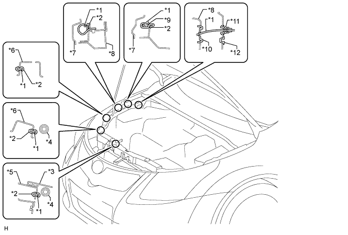
Text in Illustration *1 Hood Lock Control Cable *7 Fender Liner *2 Clamp *8 Apron *3 Clamp *9 w/ Rear Wiper:
Rear Washer Hose
*4 Bypass Hose *10 Grommet *5 Radiator Support *11 Hood Lock Control Cable Grommet *6 Radiator Support Side *12 Plug Hole -
Text in Illustration *1 Hood Lock Control Cable *2 String *3 Dash to Frame Brace *4 Engine Room Main Wire *5 Instrument Panel Wire *6 Hood Lock Control Cable Grommet After pulling the end of the hood lock control cable assembly into the cabin as shown in the illustration, remove the string.
-
-
INSTALL HOOD LOCK CONTROL LEVER SUB-ASSEMBLY
-
Connect the hood lock control cable assembly.
-
Attach the 3 claws to install the hood lock control lever sub-assembly.
-
-
INSTALL NO. 1 INSTRUMENT PANEL UNDER COVER SUB-ASSEMBLY
-
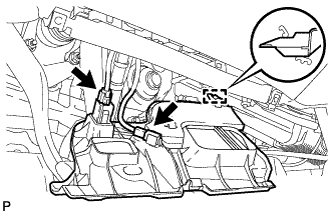
Attach the guide.
-
Connect the connectors.
-
Attach the claw to install the under cover.
-
Install the 2 screws <A>.
-
-
INSTALL HOOD LOCK ASSEMBLY
-
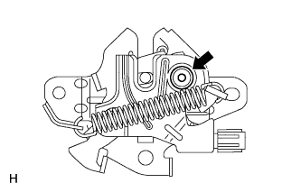
Apply MP grease to the sliding areas of the lock.
-
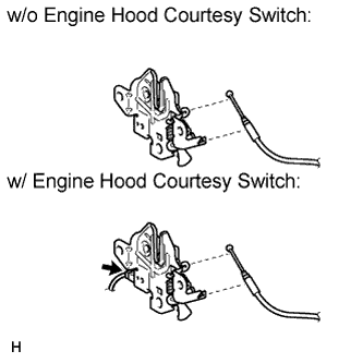
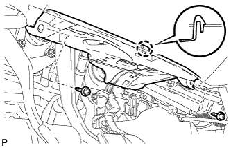
Connect the hood lock control cable.
-
Install the 3 bolts.
- Torque:
- 7.5 N*m { 76 kgf*cm, 66 in.*lbf }
-
w/ Engine Hood Courtesy Switch:
Connect the connector.
-
-
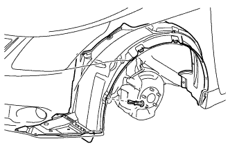
INSTALL FRONT FENDER LINER LH
-
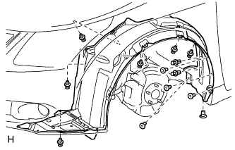
Attach the 8 clips to install the front fender liner LH.
-
Attach 5 new grommets.
-

Install the 6 screws.
-
Install the pin hold clip.
-
-
INSTALL RADIATOR SUPPORT OPENING COVER
-
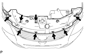
Install the radiator support opening cover with the 8 clips.
-
-
CONNECT CABLE TO NEGATIVE BATTERY TERMINAL
Note
When disconnecting the cable, some systems need to be initialized after the cable is reconnected Click here.
-
INSTALL ENGINE ROOM SIDE COVER
-
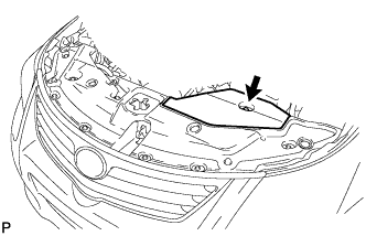
Attach the 4 clips install the engine room side cover.
-