CAN COMMUNICATION SYSTEM, Diagnostic DTC:U1002

| DTC Code | DTC Name |
|---|---|
| U1002 | Lost Communication with Gateway Module (MS Bus) |
DESCRIPTION
If 2 or more DTCs are output during the DTC check, one side of the CAN branch wire may be open (one side of the CANH [branch wire]/CANL [branch wire] of the ECU and/or sensor is open).
| DTC Code | DTC Detection Condition | Trouble Area |
|---|---|---|
| U1002 (CAN MS BUS) | Lost communication with the gateway module (MS bus). |
|
-
*: w/ Seat Position Memory System
-
For vehicles for Power Tilt and Power Telescopic Steering Column.
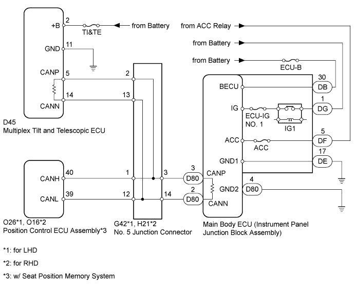
WIRING DIAGRAM
INSPECTION PROCEDURE
Note
Inspect the fuses for circuits related to this system before performing the following inspection procedure.
Tech Tips
Operating the ignition switch, any switches or any doors triggers related ECU and sensor communication with the CAN, which causes resistance variation.
PROCEDURE
-
DISCONNECT CABLE FROM NEGATIVE BATTERY TERMINAL
-
Disconnect the cable from the negative (-) battery terminal before measuring the resistances of the main wire and the branch wire.
CAUTION:
Wait at least 90 seconds after disconnecting the cable from the negative (-) battery terminal to disable the SRS system.
Note
-
w/ Navigation System (for HDD):
After the ignition switch is turned off, the HDD navigation system requires approximately a minute to record various types of memory and settings. As a result, after turning the ignition switch off, wait a minute or more before disconnecting the cable from the negative (-) battery terminal.
-
When disconnecting the cable, some systems need to be initialized after the cable is reconnected Click here.
-
NEXT 
-
-
CHECK CAN BUS WIRE (MAIN WIRE FOR DISCONNECTION, BUS LINE FOR SHORT CIRCUIT)
-
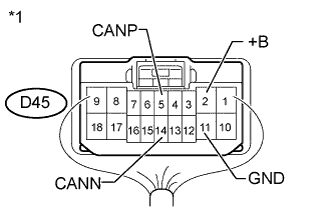
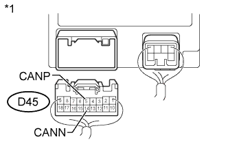
Text in Illustration *1 Component with harness connected
(Multiplex Tilt and Telescopic ECU)
Measure the resistance according to the value(s) in the table below.
Standard Resistance Tester Connection Switch Condition Specified Condition Resistance: Malfunction D45-5 (CANP) - D45-14 (CANN) Ignition switch off 54 to 69 Ω Below 54 Ω: Short in line Ignition switch off Higher than 69 Ω: Open in CAN main bus line D45-5 (CANP) - D45-2 (+B) Ignition switch off 6 kΩ or higher Below 6 kΩ: +B short D45-14 (CANN) - D45-2 (+B) Ignition switch off 6 kΩ or higher Below 6 kΩ: +B short D45-5 (CANP) - D45-11 (GND) Ignition switch off 200 Ω or higher Below 200 Ω: Ground short D45-14 (CANN) - D45-11 (GND) Ignition switch off 200 Ω or higher Below 200 Ω: Ground short Result Result Proceed to NG
- Open in CAN main bus line
A NG
- Short in line
- +B short
- Ground short
B OK C
B 
CHECK FOR SHORT IN CAN BUS WIRES (NO. 5 JUNCTION CONNECTOR - POSITION CONTROL ECU) Click here
C
CHECK FOR OPEN IN CAN BUS WIRE (NO. 5 JUNCTION CONNECTOR - POSITION CONTROL ECU) Click here
A
-
-
CHECK FOR OPEN IN CAN BUS MAIN WIRE (NO. 5 JUNCTION CONNECTOR - MULTIPLEX TILT AND TELESCOPIC ECU)
-
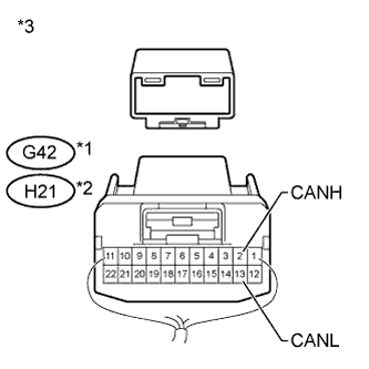
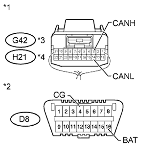
Text in Illustration *1 for LHD *2 for RHD *3 Rear view of wire harness connector
(to No. 5 Junction Connector)
Disconnect the G42*1 or H21*2 No. 5 junction connector connector.
-
*1: for LHD
-
*2: for RHD
-
-
Measure the resistance according to the value(s) in the table below.
Standard Resistance for LHD Tester Connection Switch Condition Specified Condition G42-2 (CANH) - G42-13 (CANL) Ignition switch off 108 to 132 Ω for RHD Tester Connection Switch Condition Specified Condition H21-2 (CANH) - H21-13 (CANL) Ignition switch off 108 to 132 Ω
NG
CONNECT CONNECTOR Click here
OK
-
-
CHECK FOR OPEN IN CAN BUS MAIN WIRE (NO. 5 JUNCTION CONNECTOR - MAIN BODY ECU)
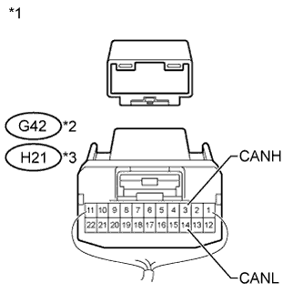
Text in Illustration *1 Rear view of wire harness connector
(to No. 5 Junction Connector)
*2 for LHD *3 for RHD
-
Measure the resistance according to the value(s) in the table below.
Standard Resistance for LHD Tester Connection Switch Condition Specified Condition G42-3 (CANH) - G42-14 (CANL) Ignition switch off 108 to 132 Ω for RHD Tester Connection Switch Condition Specified Condition H21-3 (CANH) - H21-14 (CANL) Ignition switch off 108 to 132 Ω
NG
CONNECT CONNECTOR Click here
OK 
REPAIR OR REPLACE NO. 5 JUNCTION CONNECTOR
-
-
CONNECT CONNECTOR
-
Reconnect the G42*1 or H21*2 No. 5 junction connector connector.
-
*1: for LHD
-
*2: for RHD
-
NEXT
-
-
CHECK FOR OPEN IN CAN BUS MAIN WIRE (MULTIPLEX TILT AND TELESCOPIC ECU - NO. 5 JUNCTION CONNECTOR)
-
Text in Illustration *1 Rear view of wire harness connector
(to Multiplex Tilt and Telescopic ECU)
Disconnect the D45 multiplex tilt and telescopic ECU connector.
-
Measure the resistance according to the value(s) in the table below.
Standard Resistance Tester Connection Switch Condition Specified Condition D45-5 (CANP) - D45-14 (CANN) Ignition switch off 108 to 132 Ω
NG 
REPAIR OR REPLACE CAN MAIN WIRE CONNECTED TO MULTIPLEX TILT AND TELESCOPIC ECU (MULTIPLEX TILT AND TELESCOPIC ECU - NO. 5 JUNCTION CONNECTOR)
OK
REPLACE MULTIPLEX TILT AND TELESCOPIC ECU Click here
-
-
CONNECT CONNECTOR
-
Reconnect the G42*1 or H21*2 No. 5 junction connector connector.
-
*1: for LHD
-
*2: for RHD
-
NEXT
-
-
CHECK FOR OPEN IN CAN BUS MAIN WIRE (MAIN BODY ECU - NO. 5 JUNCTION CONNECTOR)
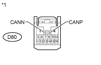
Text in Illustration *1 Front view of wire harness connector
(to Main Body ECU)
-
Disconnect the D80 main body ECU (instrument panel junction block assembly) connector.
-
Measure the resistance according to the value(s) in the table below.
Standard Resistance Tester Connection Switch Condition Specified Condition D80-3 (CANP) - D80-2 (CANN) Ignition switch off 108 to 132 Ω
NG
REPAIR OR REPLACE CAN MAIN WIRE CONNECTED TO MAIN BODY ECU (MAIN BODY ECU - NO. 5 JUNCTION CONNECTOR)
OK
REPLACE MAIN BODY ECU (INSTRUMENT PANEL JUNCTION BLOCK ASSEMBLY)
-
-
CHECK FOR SHORT IN CAN BUS WIRES (NO. 5 JUNCTION CONNECTOR - POSITION CONTROL ECU)
Note
For vehicles without a seat position memory system, go to "Check for Short in CAN Bus Wires (No. 5 Junction Connector - Multiplex Tilt and Telescopic ECU)".
-
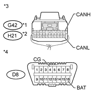
Text in Illustration *1 for LHD *2 for RHD *3 Rear view of wire harness connector
(to No. 5 Junction Connector)
*4 Front view of DLC3 Disconnect the G42*1 or H21*2 No. 5 junction connector connector.
-
*1: for LHD
-
*2: for RHD
-
-
Measure the resistance according to the value(s) in the table below.
Standard Resistance for LHD Tester Connection Switch Condition Specified Condition G42-1 (CANH) - G42-12 (CANL) Ignition switch off 200 Ω or higher G42-1 (CANH) - D8-4 (CG) Ignition switch off 200 Ω or higher G42-12 (CANL) - D8-4 (CG) Ignition switch off 200 Ω or higher G42-1 (CANH) - D8-16 (BAT) Ignition switch off 6 kΩ or higher G42-12 (CANL) - D8-16 (BAT) Ignition switch off 6 kΩ or higher for RHD Tester Connection Switch Condition Specified Condition H21-1 (CANH) - H21-12 (CANL) Ignition switch off 200 Ω or higher H21-1 (CANH) - D8-4 (CG) Ignition switch off 200 Ω or higher H21-12 (CANL) - D8-4 (CG) Ignition switch off 200 Ω or higher H21-1 (CANH) - D8-16 (BAT) Ignition switch off 6 kΩ or higher H21-12 (CANL) - D8-16 (BAT) Ignition switch off 6 kΩ or higher
NG
CONNECT CONNECTOR Click here
OK
-
-
CHECK FOR SHORT IN CAN BUS WIRES (NO. 5 JUNCTION CONNECTOR - MULTIPLEX TILT AND TELESCOPIC ECU)
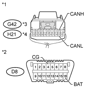
Text in Illustration *1 Rear view of wire harness connector
(to No. 5 Junction Connector)
*2 Front view of DLC3 *3 for LHD *4 for RHD
-
Measure the resistance according to the value(s) in the table below.
Standard Resistance for LHD Tester Connection Switch Condition Specified Condition G42-2 (CANH) - G42-13 (CANL) Ignition switch off 108 to 132 Ω G42-2 (CANH) - D8-4 (CG) Ignition switch off 200 Ω or higher G42-13 (CANL) - D8-4 (CG) Ignition switch off 200 Ω or higher G42-2 (CANH) - D8-16 (BAT) Ignition switch off 6 kΩ or higher G42-13 (CANL) - D8-16 (BAT) Ignition switch off 6 kΩ or higher for RHD Tester Connection Switch Condition Specified Condition H21-2 (CANH) - H21-13 (CANL) Ignition switch off 108 to 132 Ω H21-2 (CANH) - D8-4 (CG) Ignition switch off 200 Ω or higher H21-13 (CANL) - D8-4 (CG) Ignition switch off 200 Ω or higher H21-2 (CANH) - D8-16 (BAT) Ignition switch off 6 kΩ or higher H21-13 (CANL) - D8-16 (BAT) Ignition switch off 6 kΩ or higher
NG
CONNECT CONNECTOR Click here
OK
-
-
CHECK FOR SHORT IN CAN BUS WIRES (NO. 5 JUNCTION CONNECTOR - MAIN BODY ECU)
Text in Illustration *1 Rear view of wire harness connector
(to No. 5 Junction Connector)
*2 Front view of DLC3 *3 for LHD *4 for RHD
-
Measure the resistance according to the value(s) in the table below.
Standard Resistance for LHD Tester Connection Switch Condition Specified Condition G42-3 (CANH) - G42-14 (CANL) Ignition switch off 108 to 132 Ω G42-3 (CANH) - D8-4 (CG) Ignition switch off 200 Ω or higher G42-14 (CANL) - D8-4 (CG) Ignition switch off 200 Ω or higher G42-3 (CANH) - D8-16 (BAT) Ignition switch off 6 kΩ or higher G42-14 (CANL) - D8-16 (BAT) Ignition switch off 6 kΩ or higher for RHD Tester Connection Switch Condition Specified Condition H21-3 (CANH) - H21-14 (CANL) Ignition switch off 108 to 132 Ω H21-3 (CANH) - D8-4 (CG) Ignition switch off 200 Ω or higher H21-14 (CANL) - D8-4 (CG) Ignition switch off 200 Ω or higher H21-3 (CANH) - D8-16 (BAT) Ignition switch off 6 kΩ or higher H21-14 (CANL) - D8-16 (BAT) Ignition switch off 6 kΩ or higher
NG
CONNECT CONNECTOR Click here
OK
REPAIR OR REPLACE NO. 5 JUNCTION CONNECTOR
-
-
CONNECT CONNECTOR
-
Reconnect the G42*1 or H21*2 No. 5 junction connector connector.
-
*1: for LHD
-
*2: for RHD
-
NEXT
-
-
CHECK FOR SHORT IN CAN BUS WIRES (POSITION CONTROL ECU)
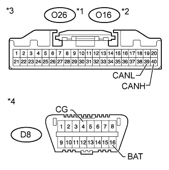
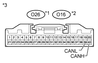
Text in Illustration *1 for LHD *2 for RHD *3 Front view of wire harness connector
(to Position Control ECU Assembly)
*4 Front view of DLC3
-
Disconnect the O26*1 or O16*2 position control ECU assembly connector.
-
*1: for LHD
-
*2: for RHD
-
-
Measure the resistance according to the value(s) in the table below.
Standard Resistance for LHD Tester Connection Switch Condition Specified Condition O26-40 (CANH) - O26-39 (CANL) Ignition switch off 200 Ω or higher O26-40 (CANH) - D8-4 (CG) Ignition switch off 200 Ω or higher O26-39 (CANL) - D8-4 (CG) Ignition switch off 200 Ω or higher O26-40 (CANH) - D8-16 (BAT) Ignition switch off 6 kΩ or higher O26-39 (CANL) - D8-16 (BAT) Ignition switch off 6 kΩ or higher for RHD Tester Connection Switch Condition Specified Condition O16-40 (CANH) - O16-39 (CANL) Ignition switch off 200 Ω or higher O16-40 (CANH) - D8-4 (CG) Ignition switch off 200 Ω or higher O16-39 (CANL) - D8-4 (CG) Ignition switch off 200 Ω or higher O16-40 (CANH) - D8-16 (BAT) Ignition switch off 6 kΩ or higher O16-39 (CANL) - D8-16 (BAT) Ignition switch off 6 kΩ or higher
NG
REPAIR OR REPLACE POSITION CONTROL ECU BRANCH WIRE OR CONNECTOR (CANH, CANL)
OK
REPLACE POSITION CONTROL ECU ASSEMBLY Click here
-
-
CONNECT CONNECTOR
-
Reconnect the G42*1 or H21*2 No. 5 junction connector connector.
-
*1: for LHD
-
*2: for RHD
-
NEXT
-
-
CHECK FOR SHORT IN CAN BUS WIRES (MULTIPLEX TILT AND TELESCOPIC ECU)
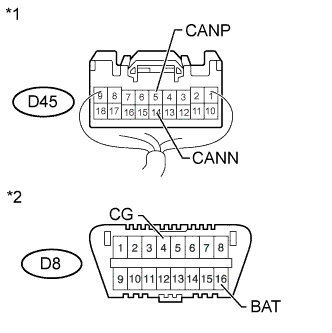
Text in Illustration *1 Rear view of wire harness connector
(to Multiplex Tilt and Telescopic ECU)
*2 Front view of DLC3
-
Disconnect the D45 multiplex tilt and telescopic ECU connector.
-
Measure the resistance according to the value(s) in the table below.
Standard Resistance Tester Connection Switch Condition Specified Condition D45-5 (CANP) - D45-14 (CANN) Ignition switch off 200 Ω or higher D45-5 (CANP) - D8-4 (CG) Ignition switch off 200 Ω or higher D45-14 (CANN) - D8-4 (CG) Ignition switch off 200 Ω or higher D45-5 (CANP) - D8-16 (BAT) Ignition switch off 200 Ω or higher D45-14 (CANN) - D8-16 (BAT) Ignition switch off 200 Ω or higher
NG
REPAIR OR REPLACE MULTIPLEX TILT AND TELESCOPIC ECU MAIN WIRE OR CONNECTOR (CANP, CANN)
OK
REPLACE MULTIPLEX TILT AND TELESCOPIC ECU Click here
-
-
CONNECT CONNECTOR
-
Reconnect the G42*1 or H21*2 No. 5 junction connector connector.
-
*1: for LHD
-
*2: for RHD
-
NEXT
-
-
CHECK FOR SHORT IN CAN BUS WIRES (MAIN BODY ECU)
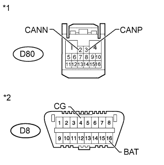
Text in Illustration *1 Front view of wire harness connector
(to Main Body ECU)
*2 Front view of DLC3
-
Disconnect the D80 main body ECU (instrument panel junction block assembly) connector.
-
Measure the resistance according to the value(s) in the table below.
Standard Resistance Tester Connection Switch Condition Specified Condition D80-3 (CANP) - D80-2 (CANN) Ignition switch off 200 Ω or higher D80-3 (CANP) - D8-4 (CG) Ignition switch off 200 Ω or higher D80-2 (CANN) - D8-4 (CG) Ignition switch off 200 Ω or higher D80-3 (CANP) - D8-16 (BAT) Ignition switch off 6 kΩ or higher D80-2 (CANN) - D8-16 (BAT) Ignition switch off 6 kΩ or higher
NG
REPAIR OR REPLACE MAIN BODY ECU MAIN WIRE OR CONNECTOR (CANP, CANN)
OK
REPLACE MAIN BODY ECU (INSTRUMENT PANEL JUNCTION BLOCK ASSEMBLY)
-
-
CHECK FOR OPEN IN CAN BUS WIRE (NO. 5 JUNCTION CONNECTOR - POSITION CONTROL ECU)
Text in Illustration *1 for LHD *2 for RHD *3 Front view of wire harness connector
(to Position Control ECU Assembly)
Note
For vehicles without a seat position memory system, go to "Check Harness or Connector (Main Body ECU - Battery and Body Ground)".
-
Disconnect the O26*1 or O16*2 position control ECU assembly connector.
-
*1: for LHD
-
*2: for RHD
-
-
Measure the resistance according to the value(s) in the table below.
Standard Resistance for LHD Tester Connection Switch Condition Specified Condition O26-40 (CANH) - O26-39 (CANL) Ignition switch off 54 to 69 Ω for RHD Tester Connection Switch Condition Specified Condition O16-40 (CANH) - O16-39 (CANL) Ignition switch off 54 to 69 Ω
NG
REPAIR OR REPLACE CAN BRANCH WIRE CONNECTED TO POSITION CONTROL ECU (NO. 5 JUNCTION CONNECTOR - POSITION CONTROL ECU)
OK
-
-
CHECK HARNESS AND CONNECTOR (MAIN BODY ECU - BATTERY AND GROUND)
-
Connect the cable to the negative (-) battery terminal.
Note
When disconnecting the cable, some systems need to be initialized after the cable is reconnected Click here.
-
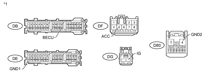
Disconnect the D80, DB, DE, DF and DG main body ECU (instrument panel junction block assembly) connectors.
-
Measure the resistance according to the value(s) in the table below.
Standard Resistance Tester Connection Condition Specified Condition D80-4 (GND2) - Body ground Always Below 1 Ω DE-17 (GND1) - Body ground Always Below 1 Ω -
Measure the voltage according to the value(s) in the table below.
Standard Voltage Tester Connection Switch Condition Specified Condition DB-30 (BECU) - Body ground Always 11 to 14 V DG-1 (IG) - Body ground Always 11 to 14 V DF-5 (ACC) - Body ground Ignition switch ACC 11 to 14 V Text in Illustration *1 Front view of wire harness connector
(to Main Body ECU)
NG
REPAIR OR REPLACE HARNESS OR CONNECTOR
OK
REPLACE MAIN BODY ECU (INSTRUMENT PANEL JUNCTION BLOCK ASSEMBLY)
-