GENERATOR REMOVAL

-
REMOVE FRONT DRIVE SHAFT ASSEMBLY RH
-
Remove the front drive shaft assembly RH Click here.
-
-
REMOVE ENGINE ROOM SIDE COVER
-
Remove the clip and engine room side cover.
-
-
DISCONNECT CABLE FROM NEGATIVE BATTERY TERMINAL
Note
-
w/ Navigation System (for HDD): After the ignition switch is turned off, the HDD navigation system requires approximately a minute to record various types of memory and settings. As a result, after turning the ignition switch off, wait a minute or more before disconnecting the cable from the negative (-) battery terminal.
-
When disconnecting the cable, some systems need to be initialized after the cable is reconnected Click here.
-
-
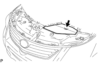
REMOVE NO. 1 ENGINE COVER
-
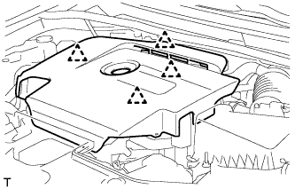
Hold the rear of the cover and slowly raise it to detach the clip on the rear of the cover. Continue to raise the cover to detach the 3 clips on the front and side of the cover and remove the cover.
Note
Attempting to disengage both front and rear clips at the same time may cause the cover to break.
-
-
REMOVE RADIATOR SUPPORT OPENING COVER
-
Remove the 8 clips and radiator support opening cover.
-
-
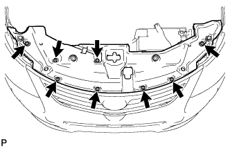
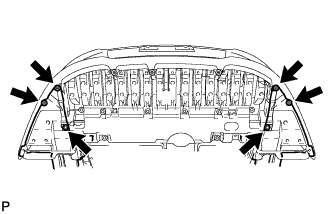
REMOVE FRONT LOWER BUMPER ABSORBER
-
Remove the 4 screws and 2 bolts.
-
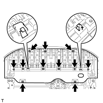
Remove the 8 bolts and 3 screws.
-
Detach the 2 hooks of the front lower bumper absorber from the installation holes on the body and remove the front lower bumper absorber.
-
-
REMOVE ENGINE UNDER COVER
-
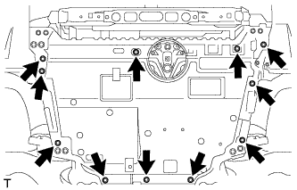
Remove the 11 clips the engine under cover.
-
-
REMOVE REAR ENGINE UNDER COVER RH
-
Remove the 5 clips and under cover.
-
-
REMOVE FRONT SUSPENSION MEMBER REINFORCEMENT RH
-
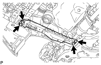
Remove the 4 bolts and front suspension member reinforcement.
-
-
REMOVE FAN AND GENERATOR V BELT
-
Using SST and a 22 mm wrench, rotate the tensioner pulley counterclockwise to loosen the belt tension. Then remove the belt.
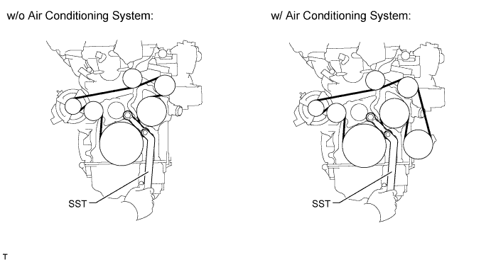
- SST
- 09216-42010
CAUTION:
-
Be careful as the wrench only fits loosely on the belt tensioner tool set point. The wrench may come off the set point and cause injuries.
-
Be careful that your hands do not become jammed between parts such as the belt, pulleys, etc.
Note
Make sure SST is installed as shown in the illustration. If not, SST and/or the belt may not be able to be removed.
-
-
REMOVE GENERATOR ASSEMBLY
-
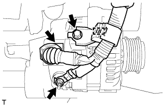
Remove the terminal cap.
-
Disconnect the generator connector and detach the clamp.
-
Remove the nut and bolt, and disconnect the generator wire.
-
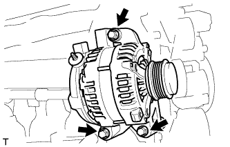
Remove the 3 bolts and generator.
-