REAR SUSPENSION MEMBER INSTALLATION

-
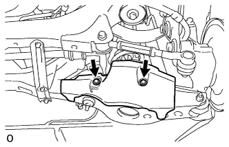
INSTALL REAR SUSPENSION MEMBER DYNAMIC DAMPER
-
Install the 2 dynamic damper to the rear suspension member with the 4 bolts.
- Torque:
- 35 N*m { 357 kgf*cm, 26 ft.*lbf }
-
-
INSTALL REAR SUSPENSION MEMBER FRONT BODY MOUNTING CUSHION (w/o Rough Road Package 2)
-
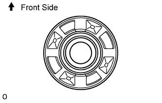
Temporarily install 2 new cushions to the rear suspension member facing in the direction shown in the illustration.
-
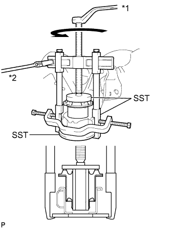
Text in Illustration *1 Turn *2 Hold Using SST, install the cushion so that there is no clearance between the suspension member and cushion.
- SST
- 09570-24011
- 09950-40011 ( 09951-04020, 09952-04010, 09953-04030, 09954-04020, 09955-04061, 09957-04010, 09958-04011 )
- 09950-60020 ( 09951-00710 )
Note
-
Apply a small amount of grease to the threads of SST (center bolt) before use.
-
Do not apply excessive pressure to the center sleeve of the cushion.
-
-
INSTALL REAR SUSPENSION MEMBER REAR BODY MOUNT CUSHION (w/o Rough Road Package 2)
-
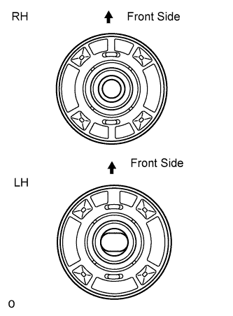
Temporarily install 2 new cushions to the rear suspension member facing in the direction shown in the illustration.
-
Text in Illustration *1 Turn *2 Hold Using SST, install the cushion so that there is no clearance between the suspension member and cushion.
- SST
- 09570-24011
- 09950-40011 ( 09951-04020, 09952-04010, 09953-04030, 09954-04020, 09955-04061, 09957-04010, 09958-04011 )
- 09950-60020 ( 09951-00710 )
Note
-
Apply a small amount of grease to the threads of SST (center bolt) before use.
-
Do not apply excessive pressure to the center sleeve of the cushion.
-
-
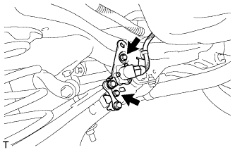
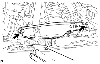
INSTALL PARKING BRAKE ACTUATOR SUPPORT BRACKET
-
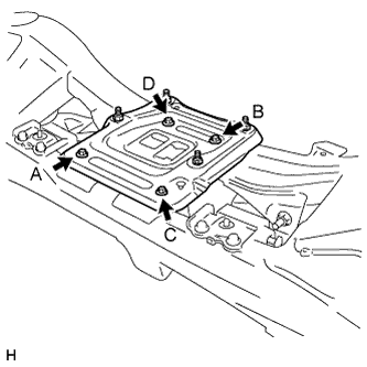
Install the parking brake actuator support bracket with the 4 bolts. Tighten the 4 bolts uniformly in alphabetical order.
- Torque:
- 35 N*m { 357 kgf*cm, 26 ft.*lbf }
-
-
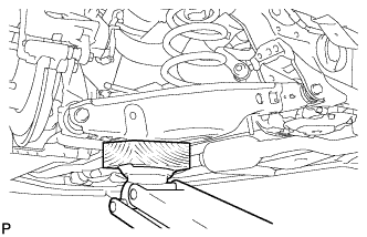
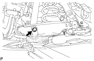
INSTALL PARKING BRAKE WITH CABLE ACTUATOR ASSEMBLY
-
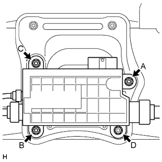
Install the actuator with the 4 nuts. Tighten the 4 nuts uniformly in alphabetical order.
- Torque:
- 25 N*m { 255 kgf*cm, 18 ft.*lbf }
Note
When handling the parking brake cable or emergency release cable, do not excessively bend or twist them. Be careful not to damage the cable or boot when installing the actuator.
-
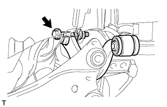
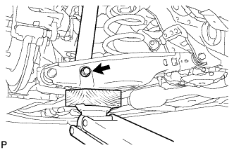
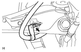
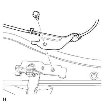
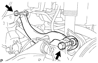
Install the 2 clamps with the 2 bolts.
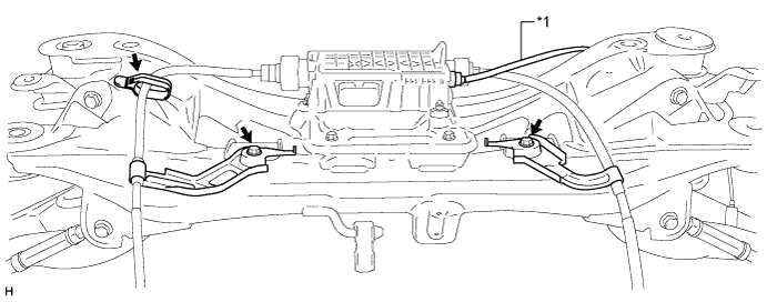
Text in Illustration *1 Emergency Release Cable - Torque:
- 35 N*m { 357 kgf*cm, 26 ft.*lbf }
Note
Make sure the emergency release cable is above the cable LH as shown in the illustration when installing the clamp to the suspension member.
-
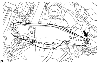
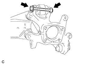
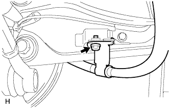
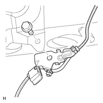
Connect the clamp to the rear suspension member.
-
-
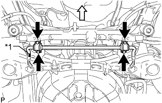
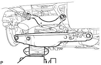
INSTALL REAR SUSPENSION MEMBER SUB-ASSEMBLY
CAUTION:
As the rear suspension member is very heavy, support it with an engine lift and attachments.
-
Lift the rear suspension member with an engine lift and attachments.
-
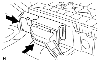
Connect the electrical parking brake actuator connector and push in the lock lever.
-
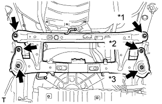
Text in Illustration *1 Bolt *2 Nut A *3 Nut B Install the rear suspension member and 8 rear suspension member stoppers with the 2 bolts and 4 nuts.
- Torque:
- for bolt
- 125 N*m { 1275 kgf*cm, 92 ft.*lbf }
- for nut A
- 61 N*m { 620 kgf*cm, 45 ft.*lbf }
- for nut B
- 125 N*m { 1275 kgf*cm, 92 ft.*lbf }
-
-
TEMPORARILY INSTALL REAR UPPER CONTROL ARM ASSEMBLY LH
-
Temporarily install the upper control arm to the rear suspension member with the bolt and nut.
-
-
TEMPORARILY INSTALL REAR UPPER CONTROL ARM ASSEMBLY RH
Tech Tips
Use the same procedure described for the LH side.
-
TEMPORARILY INSTALL REAR NO. 2 SUSPENSION ARM ASSEMBLY LH
-
Temporarily install the rear No. 2 suspension arm to the suspension member with the bolt and nut.
-
-
TEMPORARILY INSTALL REAR NO. 2 SUSPENSION ARM ASSEMBLY RH
Tech Tips
Use the same procedure described for the LH side.
-
INSTALL REAR LOWER COIL SPRING INSULATOR LH
-
INSTALL REAR LOWER COIL SPRING INSULATOR RH
-
INSTALL REAR UPPER COIL SPRING INSULATOR LH
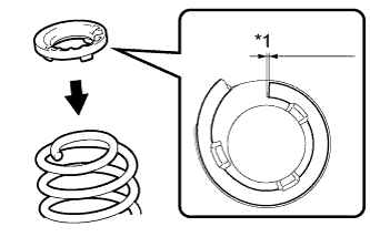
Text in Illustration *1 10 mm or less
-
Install the rear upper coil spring insulator to the rear coil spring.
Note
Install the rear upper coil insulator so that the dimension between the stopper and upper end of the rear coil spring is 10 mm (0.394 in.) or less.
-
-
INSTALL REAR UPPER COIL SPRING INSULATOR RH
Tech Tips
Use the same procedure described for the LH side.
-
INSTALL REAR COIL SPRING LH
-
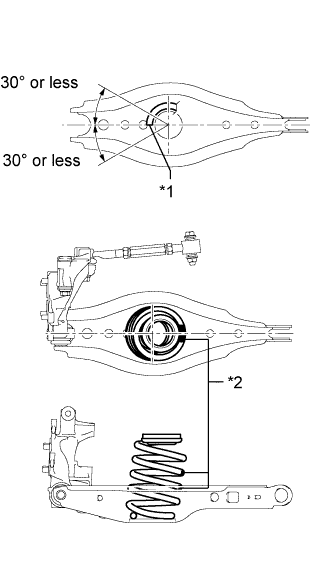
Install the rear coil spring to the rear No. 2 suspension arm.
Text in Illustration *1 End of Coil *2 Identification Mark Note
-
Install the rear coil spring so that the identification marks are positioned as shown in the illustration.
-
Install the rear coil spring so that its end is within the range shown in the illustration.
-
-

Using a jack and wooden block, raise the vehicle gradually to install the rear No. 2 suspension arm to the rear axle carrier. Then temporarily install the bolt and nut.
-
-
INSTALL REAR COIL SPRING RH
Tech Tips
Use the same procedure described for the LH side.
-
TEMPORARILY INSTALL REAR SHOCK ABSORBER ASSEMBLY LH
-
Support the rear No. 2 suspension arm assembly LH with a jack using a wooden block to avoid damage.
-
Temporarily install the rear shock absorber assembly to the rear No. 2 suspension arm with the bolt and nut.
-
-
TEMPORARILY INSTALL REAR SHOCK ABSORBER ASSEMBLY RH
Tech Tips
Use the same procedure described for the LH side.
-
INSTALL REAR AXLE CARRIER SUB-ASSEMBLY LH
-
Install the rear axle carrier to the rear upper control arm with the bolt and nut.
- Torque:
- 90 N*m { 918 kgf*cm, 66 ft.*lbf }
Note
Since a stopper nut is used, tighten the bolt.
-
-
INSTALL REAR AXLE CARRIER SUB-ASSEMBLY RH
Tech Tips
Use the same procedure described for the LH side.
-
TEMPORARILY INSTALL REAR NO. 1 SUSPENSION ARM ASSEMBLY LH
-
Temporarily install the rear No. 2 suspension arm to the suspension member with the bolt and nut.
-
-
TEMPORARILY INSTALL REAR NO. 1 SUSPENSION ARM ASSEMBLY RH
Tech Tips
Use the same procedure described for the LH side.
-
CONNECT REAR TRAILING ARM ASSEMBLY LH
-
Connect the rear trailing arm to the rear axle carrier with the 2 bolts.
- Torque:
- 200 N*m { 2039 kgf*cm, 148 ft.*lbf }
-
-
CONNECT REAR TRAILING ARM ASSEMBLY RH
Tech Tips
Use the same procedure described for the LH side.
-
INSTALL REAR STABILIZER BAR
Text in Illustration *1 Identification Mark 
Front of the Vehicle
-
Install the rear stabilizer bar and rear No. 1 stabilizer bracket LH and RH to the rear suspension member with the 4 bolts.
- Torque:
- 78 N*m { 795 kgf*cm, 58 ft.*lbf }
Note
The identification mark must be on the right side of the vehicle when installing the rear stabilizer bar.
-
-
INSTALL REAR STABILIZER LINK ASSEMBLY LH
Note
Since the rear stabilizer link, rear stabilizer cushions and lock nut are not reusable, new parts must be installed.
-
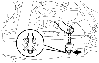
Temporarily install a new rear stabilizer link and 2 new rear stabilizer cushions to the rear No. 2 suspension arm with 2 new nuts.
-
Tighten the upper nut.
- Torque:
- 95 N*m { 969 kgf*cm, 70 ft.*lbf }
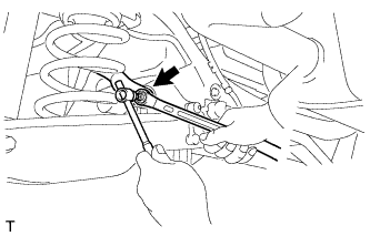
Tech Tips
If the ball joint turns together with the nut, use a 6 mm hexagon wrench to hold the stud.
-
Tighten the lower lock nut.
- Torque:
- 30 N*m { 306 kgf*cm, 22 ft.*lbf }
-
-
INSTALL REAR STABILIZER LINK ASSEMBLY RH
Tech Tips
Use the same procedure described for the LH side.
-
INSTALL REAR SUSPENSION MEMBER BRACE LH
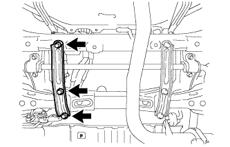
-
Install the rear suspension member brace to the rear suspension member with the 3 bolts.
- Torque:
- 32 N*m { 326 kgf*cm, 24 ft.*lbf }
-
-
INSTALL REAR SUSPENSION MEMBER BRACE RH
Tech Tips
Use the same procedure described for the LH side.
-
INSTALL REAR FLOOR SIDE MEMBER COVER RH
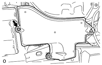
-
Attach the 2 clips to install the rear floor side member cover RH, and then install the bolt.
- Torque:
- 13 N*m { 127 kgf*cm, 9 ft.*lbf }
-
-
INSTALL REAR SUSPENSION ARM COVER LH
-
Install the cover with the 2 bolts.
- Torque:
- 10 N*m { 102 kgf*cm, 7 ft.*lbf }
-
-
INSTALL REAR SUSPENSION ARM COVER RH
Tech Tips
Use the same procedure described for the LH side.
-
INSTALL REAR HEIGHT CONTROL SENSOR SUB-ASSEMBLY (for HID Headlight)
-
Install the rear height control sensor with the 2 bolts.
- Torque:
- 14 N*m { 143 kgf*cm, 10 ft.*lbf }
-
Connect the connector.
-
-
INSTALL REAR AXLE HUB AND BEARING ASSEMBLY LH
-
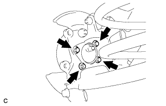
Install the rear axle hub and bearing assembly with the 4 bolts.
- Torque:
- 90 N*m { 918 kgf*cm, 66 ft.*lbf }
-
-
INSTALL REAR AXLE HUB AND BEARING ASSEMBLY RH
Tech Tips
Use the same procedure described for the LH side.
-
INSTALL REAR DISC
-
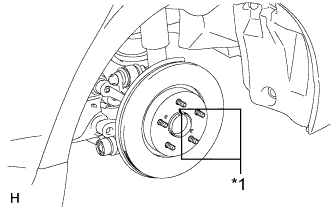
Text in Illustration *1 Matchmark Align the matchmarks of the disc and axle hub and install the disc.
Note
When replacing the disc with a new one, select the installation position where the rear disc has minimal runout.
-
-
CONNECT REAR DISC BRAKE CALIPER ASSEMBLY LH
-
Install the rear disc brake cylinder assembly Click here.
-
-
CONNECT REAR DISC BRAKE CALIPER ASSEMBLY RH
Tech Tips
Use the same procedure described for the LH side.
-
CONNECT PARKING BRAKE CABLE AND EMERGENCY RELEASE CABLE
-
Install the clamp to the trailing arm RH with the bolt.
- Torque:
- 6.0 N*m { 61 kgf*cm, 53 in.*lbf }
-
Install the clamp to the trailing arm LH with the bolt.
- Torque:
- 6.0 N*m { 61 kgf*cm, 53 in.*lbf }
-
Install the casing cap with the 2 nuts.
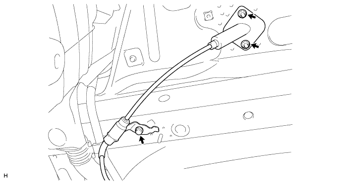
- Torque:
- 9.0 N*m { 92 kgf*cm, 80 in.*lbf }
Note
Be careful not to damage the casing cap gasket when installing the casing cap.
-
Install the clamp with the bolt.
- Torque:
- 6.0 N*m { 61 kgf*cm, 53 in.*lbf }
-
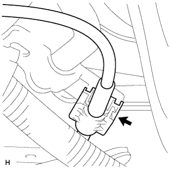
Install a new clamp.
Note
Make sure that the clamp contacts the clamp ring on the cable.
-
-
INSTALL FLOOR NO. 2 UNDER COVER
-
Install the floor No. 2 under cover with the 6 clips.
-
-
CONNECT SKID CONTROL SENSOR WIRE
Note
To prevent interference with other parts, do not twist the painted line areas of the sensor wire when installing it.
-

Connect the skid control sensor wire connector to the skid control sensor.
-
Attach the sensor clamp.
Note
Do not twist the sensor wire when installing the clamp.
-
Install the sensor clamp with the bolt.
- Torque:
- 8.5 N*m { 87 kgf*cm, 75 in.*lbf }
Note
Do not twist the sensor wire when installing the clamp.
-
Install the sensor clamp with the bolt.
- Torque:
- 8.5 N*m { 87 kgf*cm, 75 in.*lbf }
Note
Do not twist the sensor wire when installing the clamp.
-
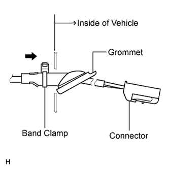
Insert the connector and grommet into the inside of the vehicle through the hole in the wheel house.
Note
Make sure the band clamp remains on the outside of the vehicle.
-
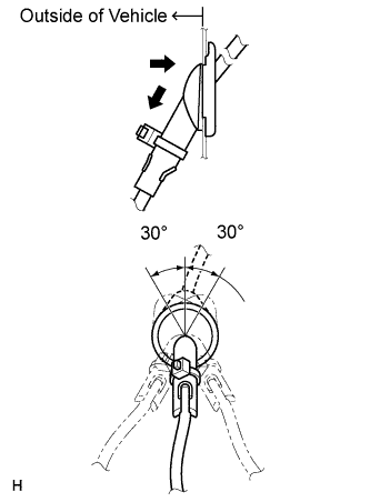
Hold the grommet and pull it toward the outside of the vehicle. Then fix the grommet in place so that it is not tilted.
Note
-
When pulling out the grommet, do not grip the sensor wire.
-
Fix the grommet in place within the range shown in the illustration.
-
-
Connect the skid control sensor wire connector to the vehicle side connector on the rear floor.
-
-
INSTALL TAILPIPE ASSEMBLY
-
for 1AD-FTV:
Install the tailpipe assembly Click here.
-
for 2AD-FTV:
Install the tailpipe assembly Click here.
-
for 2AD-FHV:
Install the tailpipe assembly Click here.
-
-
STABILIZE SUSPENSION
-
Install the rear wheel.
- Torque:
- 103 N*m { 1050 kgf*cm, 76 ft.*lbf }
-
Lower the vehicle and bounce it up and down several times to stabilize the rear suspension.
-
Remove the rear wheel.
-
-
TIGHTEN REAR SHOCK ABSORBER ASSEMBLY LH
-
Tighten the bolt of the rear shock absorber.
- Torque:
- 90 N*m { 918 kgf*cm, 66 ft.*lbf }
Note
Since a stopper nut is used, tighten the bolt.
-
-
TIGHTEN REAR SHOCK ABSORBER ASSEMBLY RH
Tech Tips
Use the same procedure described for the LH side.
-
TIGHTEN REAR UPPER CONTROL ARM ASSEMBLY LH
-
Using a jack and wooden block, raise the vehicle so that the rear No. 2 suspension arm assembly LH is at the standard vehicle height to apply load to the rear suspension.
-
Tighten the 2 bolts and 2 nuts of the upper control arm.
- Torque:
- 90 N*m { 918 kgf*cm, 66 ft.*lbf }
Note
Since a stopper nut is used, tighten the bolt.
-
-
TIGHTEN REAR UPPER CONTROL ARM ASSEMBLY RH
Tech Tips
Use the same procedure described for the LH side.
-
TIGHTEN REAR NO. 2 SUSPENSION ARM ASSEMBLY LH
-
Tighten the 2 bolts and 2 nuts of the rear No. 2 suspension arm assembly.
- Torque:
- 90 N*m { 918 kgf*cm, 66 ft.*lbf }
Note
Since a stopper nut is used, tighten the bolt.
-
-
TIGHTEN REAR NO. 2 SUSPENSION ARM ASSEMBLY RH
Tech Tips
Use the same procedure described for the LH side.
-
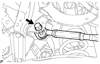
TIGHTEN REAR NO. 1 SUSPENSION ARM ASSEMBLY LH
-
for Turnbuckle Type:
-
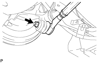
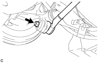
Tighten the nut of the rear No. 1 suspension arm.
- Torque:
- 100 N*m { 1020 kgf*cm, 74 ft.*lbf }
-
Tighten the bolt and nut of the rear No. 1 suspension arm.
- Torque:
- 90 N*m { 918 kgf*cm, 66 ft.*lbf }
Note
Since a stopper nut is used, tighten the bolt.
-
-
for Cam Type:
-
Tighten the nut of the rear No. 1 suspension arm.
- Torque:
- 100 N*m { 1020 kgf*cm, 74 ft.*lbf }
-
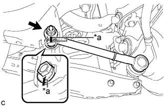
Text in Illustration *a Matchmarks Align the matchmarks on the No. 2 camber adjust cam, rear suspension toe adjust cam sub-assembly and rear suspension member sub-assembly.
-
Fully tighten the nut to install the rear No. 1 suspension arm assembly.
- Torque:
- 100 N*m { 1020 kgf*cm, 74 ft.*lbf }
Note
Hold the rear suspension toe adjust cam sub-assembly while rotating the nut.
-
-
-
TIGHTEN REAR NO. 1 SUSPENSION ARM ASSEMBLY RH
Tech Tips
Use the same procedure described for the LH side.
-
CONNECT CABLE TO NEGATIVE BATTERY TERMINAL
Note
When disconnecting the cable, some systems need to be initialized after the cable is reconnected Click here.
-
INSTALL REAR WHEEL
- Torque:
- 103 N*m { 1050 kgf*cm, 76 ft.*lbf }
-
INSPECT FOR EXHAUST GAS LEAK
-
INSPECT AND ADJUST REAR WHEEL ALIGNMENT
-
Inspect and adjust the rear wheel alignment Click here.
-
-
ADJUST HEADLIGHT ASSEMBLY
-
for Halogen Headlight:
Adjust the headlight assembly Click here.
-
for HID Headlight:
Adjust the headlight assembly Click here.
-
-
INSPECT SPEED SENSOR SIGNAL
-
Inspect the speed sensor signal Click here.
-
-
PERFORM CALIBRATION
-
Clear the electric parking brake ECU memory and perform yaw rate sensor and clutch pedal stroke sensor zero point calibration Click here.
-