UPPER INSTRUMENT PANEL INSTALLATION

Tech Tips
-
Use the same procedure for RHD and LHD vehicles.
-
The procedure listed below is for LHD vehicles.
-
A bolt without a torque specification is shown in the standard bolt chart Click here.
-
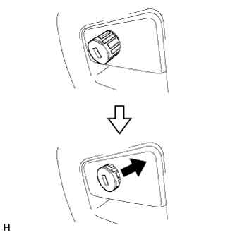
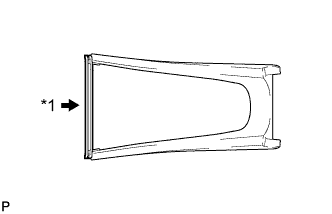
INSTALL GLOVE COMPARTMENT DOOR LOCK CYLINDER ASSEMBLY (w/ Key Cylinder)
-
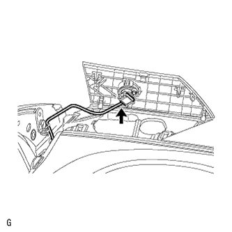
Insert the bottom side of the glove compartment door lock cylinder as shown in the illustration, hold down the stopper and install the glove compartment door lock cylinder.
-
-
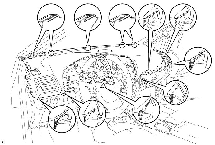
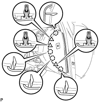
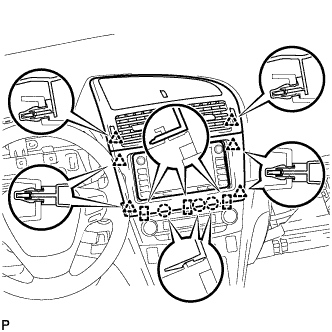
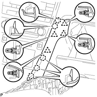
INSTALL UPPER INSTRUMENT PANEL SUB-ASSEMBLY
-
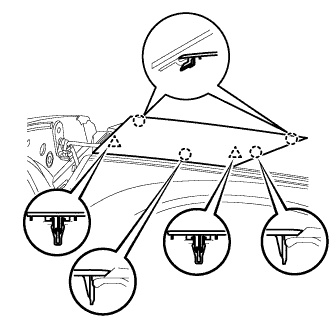
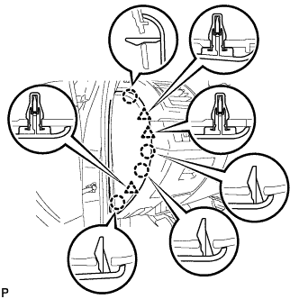
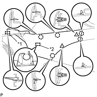
Securely attach the 6 claws and 4 clips of the instrument panel to the vehicle body.
-
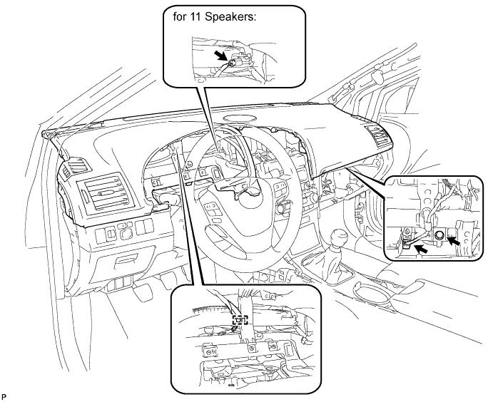
Install the instrument panel with the 3 screws <C>.
-
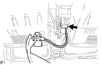
Install the passenger airbag bolt <A>.
- Torque:
- 20 N*m { 204 kgf*cm, 15 ft.*lbf }
-
Connect the connectors and clamp.
-
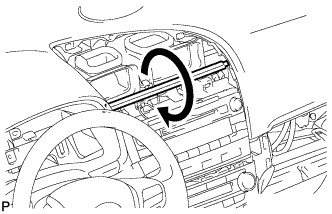
When replacing the upper instrument panel sub-assembly with a new one:
-
Twist the rib (the piece used to maintain the shape of the panel) in the direction of the arrow in the illustration until it detaches from the instrument panel, and remove the rib.
-
-
-
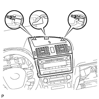
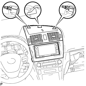
INSTALL NO. 2 INSTRUMENT PANEL SPEAKER PANEL SUB-ASSEMBLY (for 11 Speakers)
-
Attach the 2 clips and 3 claws to install the speaker panel.
-
-
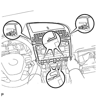
INSTALL NO. 2 INSTRUMENT PANEL SPEAKER PANEL SUB-ASSEMBLY
-
Connect the speaker connector.
-
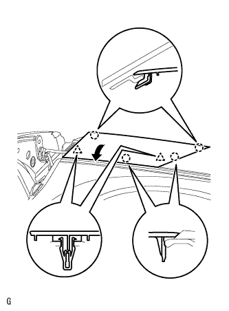
Set the 2 claws on the side of the speaker panel towards the front of the vehicle in place and using them as pivot points, lower the panel in the direction indicated by the arrow in the illustration, and then attach the claws and clips to the instrument panel to install the speaker panel.
-
-
INSTALL NO. 1 INSTRUMENT PANEL SPEAKER PANEL SUB-ASSEMBLY (for 11 Speakers)
Tech Tips
Use the same procedure described for the No. 2 instrument panel speaker panel.
-
INSTALL NO. 1 INSTRUMENT PANEL SPEAKER PANEL SUB-ASSEMBLY
Tech Tips
Use the same procedure described for the No. 2 instrument panel speaker panel.
-
INSTALL FRONT PILLAR GARNISH LH (for Sedan)
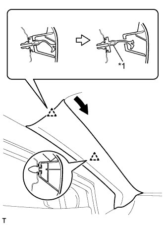
Text in Illustration *1 Front Pillar Garnish Clip
-
Pull the upper part of the garnish toward the inside of the cabin and detach the 2 clips.
Tech Tips
Make the front pillar garnish hang down from the front pillar garnish clip.
-
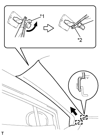
Text in Illustration *1 Front Pillar Garnish Clip *2 Protective Tape Turn the end of the front pillar garnish clip 90° with needle-nosed pliers and remove it from the front pillar garnish.
Note
-
Front pillar garnish clips are reusable if they are not removed from the vehicle and have no damage.
-
Replace the front pillar garnish clips with new ones if they are removed from the vehicle.
Tech Tips
Tape the needle-nosed pliers tip before use.
-
-
Detach the 2 guides and remove the front pillar garnish.
-

Text in Illustration *1 Curtain Shield Airbag Assembly *2 Adhesive Tape *3 Protective Cover w/ Curtain Shield Airbag:
Protect the curtain shield airbag assembly.
-
Completely cover the airbag with a cloth or nylon sheet and secure the ends of the cover with adhesive tape as shown in the illustration.
Note
Cover the curtain shield airbag with a protective cover as soon as the front pillar garnish is removed.
-
-
-
INSTALL FRONT PILLAR GARNISH LH (for Wagon)
Text in Illustration *1 Front Pillar Garnish Clip
-
Pull the upper part of the garnish toward the inside of the cabin and detach the 2 clips.
Tech Tips
Make the front pillar garnish hang down from the front pillar garnish clip.
-
Text in Illustration *1 Front Pillar Garnish Clip *2 Protective Tape Turn the end of the front pillar garnish clip 90° with needle-nosed pliers and remove it from the front pillar garnish.
Note
-
Front pillar garnish clips are reusable if they are not removed from the vehicle and have no damage.
-
Replace the front pillar garnish clips with new ones if they are removed from the vehicle.
Tech Tips
Tape the needle-nosed pliers tip before use.
-
-
Detach the 2 guides and remove the front pillar garnish.
-
Text in Illustration *1 Curtain Shield Airbag Assembly *2 Adhesive Tape *3 Protective Cover Protect the curtain shield airbag assembly.
-
Completely cover the airbag with a cloth or nylon sheet and secure the ends of the cover with adhesive tape as shown in the illustration.
Note
Cover the curtain shield airbag with a protective cover as soon as the front pillar garnish is removed.
-
-
-
INSTALL FRONT PILLAR GARNISH RH (for Sedan)
Tech Tips
Use the same procedure described for the LH side.
-
INSTALL FRONT PILLAR GARNISH RH (for Wagon)
Tech Tips
Use the same procedure described for the LH side.
-
INSTALL INSTRUMENT SIDE PANEL LH
-
Attach the 2 hooks.
-
Attach the 3 clips and 4 claws to install the side panel.
-
-
INSTALL INSTRUMENT SIDE PANEL RH
-
Text in Illustration *1 w/ Airbag Cut Off Switch Cylinder Attach the 2 hooks.
-
w/ Airbag Cut Off Switch Cylinder:
-
Connect the connector.
-
-
Attach the 3 clips and 4 claws to install the side panel.
-
-
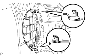
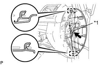
INSTALL CENTER INSTRUMENT PANEL REGISTER ASSEMBLY WITH FINISH PANEL (for Audio-less, DVD Navigation System)
-
Connect the connector and clamp.
-
Attach the 2 clips and hook.
-
Attach the 2 clips.
-
Attach the 3 claws and 3 hooks to install the panel register.
-
-
INSTALL CENTER INSTRUMENT PANEL REGISTER ASSEMBLY WITH FINISH PANEL (for Audio, HDD Navigation System)
-
Connect the connector and clamp.
-
Attach the 2 clips and hook.
-
Attach the 6 clips.
-
Attach the 3 claws and 3 hooks to install the panel register.
-
-
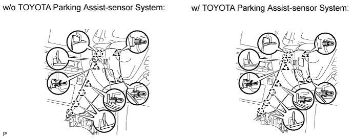
INSTALL INSTRUMENT PANEL FINISH PANEL END RH (for RHD)
-
w/o TOYOTA Parking Assist-sensor System:
-
Attach the 4 clips and 5 claws to install the panel end.
-
-
w/ TOYOTA Parking Assist-sensor System:
-
Connect the connector.
-
Attach the 4 clips and 5 claws to install the panel end.
-
-
-
INSTALL GLOVE COMPARTMENT DOOR ASSEMBLY
-
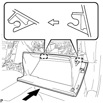
Attach the 2 hinges to install the door.
-
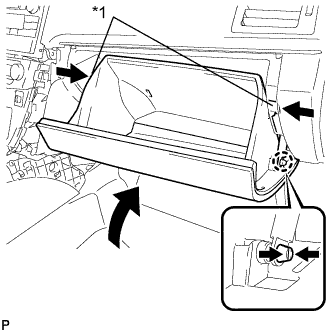
Text in Illustration *1 Stopper While pushing in the sides of the glove compartment door as indicated by the arrows in the illustration, close the door to engage the 2 stoppers.
-
-
INSTALL INSTRUMENT PANEL FINISH PANEL END RH (for LHD)
-
Attach the 4 clips and 5 claws to install the panel end.
-
-
INSTALL INSTRUMENT PANEL FINISH PANEL END LH
-
Attach the 4 clips and 5 claws to install the panel end.
-
-
INSTALL NO. 3 BOX PANEL (w/ Console Box Lid)
-
When replacing the No. 3 box panel with a new one:
-
Text in Illustration *1 Cut Cut off the rib (the piece used to maintain the shape of the panel) shown in the illustration.
-
-
Attach the 6 clips to install the box panel.
-
-
INSTALL NO. 3 BOX PANEL (w/o Console Box Lid)
-
When replacing the No. 3 box panel with a new one:
-
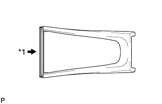
Text in Illustration *1 Cut Cut off the rib (the piece used to maintain the shape of the panel) shown in the illustration.
-
-
Attach the 6 clips to install the box panel.
-
-
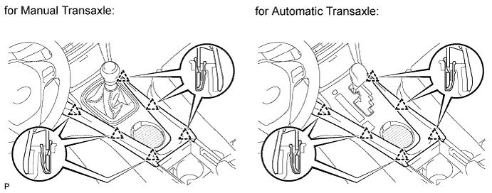
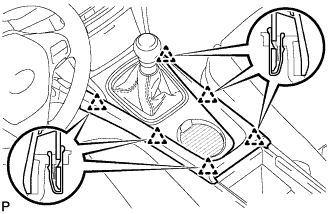
INSTALL LOWER NO. 1 INSTRUMENT PANEL FINISH PANEL
-
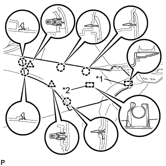
Text in Illustration *1 Guide *2 Clamp Attach the guide near the front of the vehicle.
-
Attach the clamp.
-
Attach the 2 clips and 5 claws to install the finish panel.
-
-
INSTALL LOWER NO. 2 INSTRUMENT PANEL FINISH PANEL
-
Text in Illustration *1 Guide *2 Clamp Attach the guide near the front of the vehicle.
-
Attach the clamp.
-
Attach the 2 clips and 5 claws to install the finish panel.
-
-
INSTALL COMBINATION METER ASSEMBLY
-
Install the combination meter assembly Click here.
-
-
CONNECT CABLE TO NEGATIVE BATTERY TERMINAL
Note
When disconnecting the cable, some systems need to be initialized after the cable is reconnected Click here.
-
RESTORE AUTOAWAY/RETURN FUNCTION (for Power Tilt and Power Telescopic Steering Column)
-
Restore the Autoaway/Return function setting to the previous condition by changing the customize parameter Click here.
-
-
CHECK SRS WARNING LIGHT
-
Check the SRS warning light Click here.
-