AIR CONDITIONING UNIT (for Automatic Air Conditioning System) INSTALLATION

Tech Tips
-
Use the same procedure for LHD and RHD vehicles.
-
The procedure listed below is for LHD vehicles.
-
A bolt without a torque specification is shown in the standard bolt chart Click here.
-
INSTALL AIR CONDITIONING UNIT ASSEMBLY
-
Install the air conditioning unit with the nut and bolt.
- Torque:
- 9.8 N*m { 100 kgf*cm, 87 in.*lbf }
-
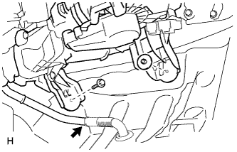
Connect the drain cooler hose.
-
-
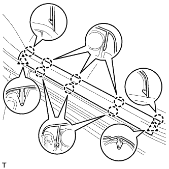
INSTALL INSTRUMENT PANEL REINFORCEMENT ASSEMBLY
-
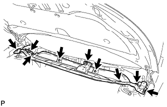
Install the instrument panel reinforcement.
-
Install the instrument panel reinforcement with the bolts and screws.
-
-
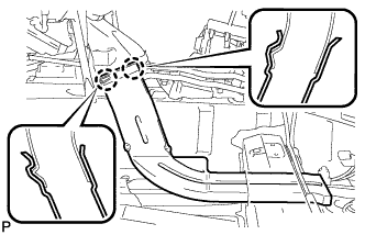
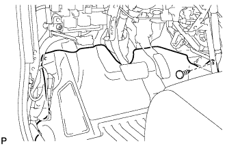
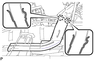
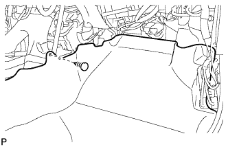
Attach the clamps and connectors to attach the wire harness.
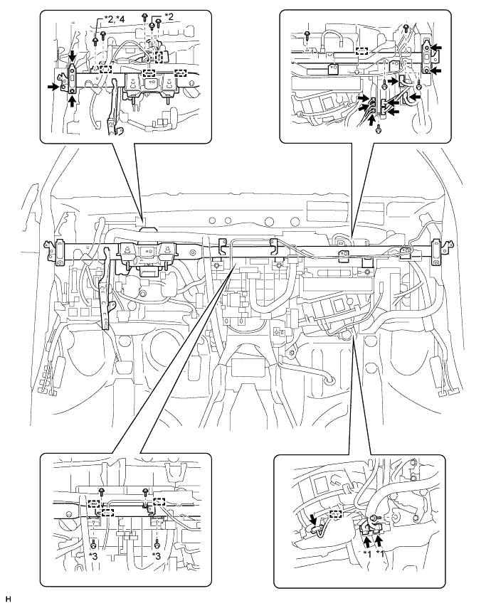
Text in Illustration *1 w/ PTC Heater *3 9.8 N*m (100 kgf*cm, 87 in.*lbf) *2 24 N*m (245 kgf*cm, 18 ft.*lbf) *4 for Manual Transaxle
-
-
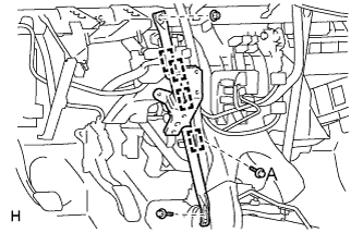
INSTALL NO. 1 INSTRUMENT PANEL BRACE SUB-ASSEMBLY
-
Install the brace with the 2 bolts and nut.
- Torque:
- for Bolt A
- 9.8 N*m { 100 kgf*cm, 87 in.*lbf }
-
Attach the 4 clamps.
-
-
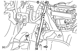
INSTALL NO. 2 INSTRUMENT PANEL BRACE SUB-ASSEMBLY
-
Install the brace with the 2 bolts and nut.
- Torque:
- for Bolt A
- 9.8 N*m { 100 kgf*cm, 87 in.*lbf }
-
Attach the clamp.
-
-
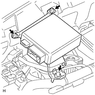
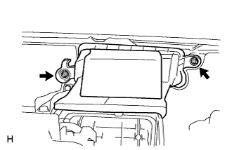
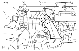
INSTALL MAIN BODY ECU (INSTRUMENT PANEL JUNCTION BLOCK ASSEMBLY)
-
Install the main body ECU with the 2 bolts.
-
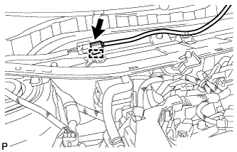
Connect the 3 connectors.
-
-
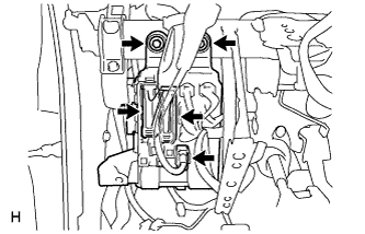
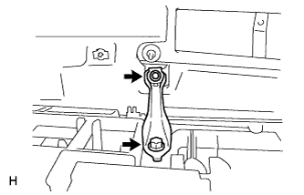
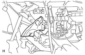
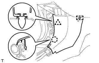
INSTALL POWER STEERING ECU ASSEMBLY
-
Install the power steering ECU with the bolt and 2 nuts.
- Torque:
- 8.0 N*m { 82 kgf*cm, 71 in.*lbf }
-
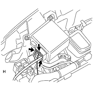
Connect the 3 connectors to the power steering ECU.
-
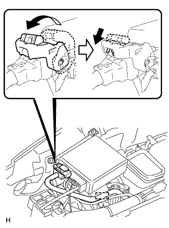
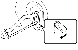
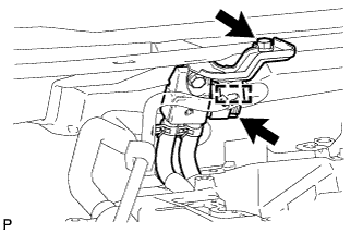
Connect the connector to the power steering ECU.
-
As shown in the illustration, return the lock lever to its original position to connect the connector and securely push in the lock of the lock lever.
-
Attach the wire harness clamp to the power steering ECU.
-
-
INSTALL CENTER INSTRUMENT PANEL TO COWL BRACE
-
Install the brace with the 2 bolts.
-
-
INSTALL AIR DUCT ASSEMBLY
-
Install the duct with the 2 nuts.
- Torque:
- 9.8 N*m { 100 kgf*cm, 87 in.*lbf }
-
-
INSTALL DEFROSTER NOZZLE ASSEMBLY
-
Attach the 4 claws to install the defroster nozzle assembly.
-
w/ Navigation System:
Install the navigation antenna assembly.
-
Attach the claw to install the navigation antenna assembly.
-
Install the 2 screws.
-
-
-
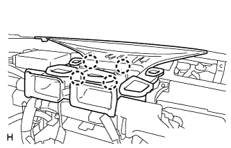
INSTALL COOLER (SOLAR SENSOR) THERMISTOR
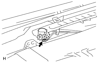
-
Attach the 2 claws to install the sensor.
-
Connect the connector.
-
-
INSTALL STEERING COLUMN ASSEMBLY
-
for Manual Tilt and Manual Telescopic Steering Column:
Install the steering column Click here.
-
for Power Tilt and Power Telescopic Steering Column:
Install the steering column Click here.
-
-
INSTALL NO. 3 AIR DUCT SUB-ASSEMBLY (for Driver Side)
-
Attach the 2 claws to install the duct.
-
-
INSTALL NO. 3 AIR DUCT SUB-ASSEMBLY (for Front Passenger Side)
-
Attach the 2 claws to install the duct.
-
-
INSTALL REAR NO. 1 AIR DUCT
-
Attach the 4 claws to install the rear No. 1 air duct.
-
-
INSTALL REAR NO. 2 AIR DUCT
-
Attach the 2 claws to install the rear No. 2 air duct.
-
Install the floor carpet with the clip.
-
-
INSTALL REAR NO. 3 AIR DUCT
-
Attach the 2 claws to install the rear No. 3 air duct.
-
Install the floor carpet with the clip.
-
-
INSTALL COWL SIDE TRIM BOARD LH
-
Attach the clip, claw and guide to install the cowl side trim board.
-
-
INSTALL COWL SIDE TRIM BOARD RH
Tech Tips
Use the same procedure described for the LH side.
-
INSTALL FRONT DOOR SCUFF PLATE LH
-
Attach the 2 clips and 8 claws to install the front door scuff plate.
-
-
INSTALL FRONT DOOR SCUFF PLATE RH
Tech Tips
Use the same procedure described for the LH side.
-
INSTALL LOWER INSTRUMENT PANEL SUB-ASSEMBLY
-
Install the lower instrument panel Click here.
-
-
INSTALL UPPER INSTRUMENT PANEL SUB-ASSEMBLY
-
Install the upper instrument panel Click here.
-
-
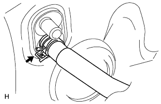
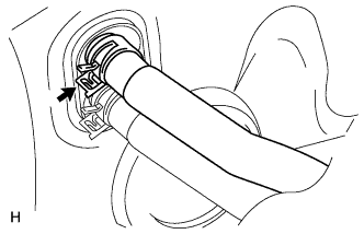
CONNECT HEATER WATER INLET HOSE A
-
Connect the heater water inlet hose.
-
Using pliers, grip the claws of the clip and slide the clip.
-
-
CONNECT HEATER WATER OUTLET HOSE A
-
Connect the heater water outlet hose.
-
Using pliers, grip the claws of the clip and slide the clip.
-
-
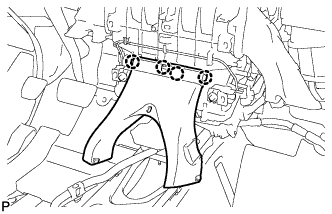
CONNECT AIR CONDITIONING TUBE ASSEMBLY
-
Remove the attached vinyl tape from the tubes.
-
Sufficiently apply compressor oil to 2 new O-rings and the fitting surface of the air conditioning tube assembly.
Compressor oil ND-OIL 8 or equivalent -
Install the 2 O-rings to the air conditioning tube assembly.
-
Connect the air conditioning tube assembly.
-
Attach the plate as shown in the illustration and install the bolt.
- Torque:
- 9.8 N*m { 100 kgf*cm, 87 in.*lbf }
-
-
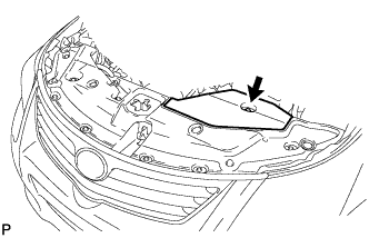
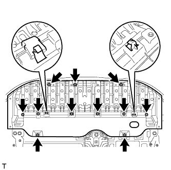
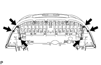
INSTALL COWL TOP OUTER PANEL
-
Install the outer cowl top panel with the 9 bolts.
- Torque:
- 8.8 N*m { 90 kgf*cm, 78 in.*lbf }
-
Attach the clamp and connect the connector.
-
-
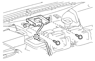
INSTALL DIFFERENTIAL PRESSURE SENSOR ASSEMBLY (for DPF)
-
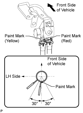
Connect the 2 vacuum hoses.
Note
Connect the vacuum hoses so that the painted marks of the 2 vacuum hoses are as shown in the illustration.
-
Install the sensor with the bolt.
- Torque:
- 8.0 N*m { 82 kgf*cm, 71 in.*lbf }
-
Connect the sensor connector and attach the wire harness clamp.
-
-
INSTALL FRONT WIPER MOTOR AND BRACKET
-
Install the front wiper motor and bracket Click here.
-
-
CONNECT CABLE TO NEGATIVE BATTERY TERMINAL
Note
When disconnecting the cable, some systems need to be initialized after the cable is reconnected Click here.
-
CHECK SRS WARNING LIGHT
-
Check the SRS warning light Click here.
-
-
ADD ENGINE COOLANT
-
for 1AD-FTV:
Add engine coolant Click here.
-
for 2AD-FHV:
Add engine coolant Click here.
-
for 2AD-FTV:
Add engine coolant Click here.
-
-
CHARGE REFRIGERANT
- SST
- 09985-20010 ( 09985-02130, 09985-02150, 09985-02090, 09985-02110, 09985-02010, 09985-02050, 09985-02060, 09985-02070 )
-
Perform vacuum purging using a vacuum pump.
-
Charge refrigerant HFC-134a (R134a).
Standard 440 +/-30 g (15.5 +/-1.1 oz) 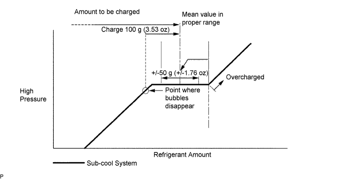
Note
-
Do not operate the cooler compressor before charging refrigerant as the cooler compressor will not work properly without any refrigerant, and will overheat.
-
Approximately 200 g (7.05 oz) of refrigerant may need to be charged after bubbles disappear. The refrigerant amount should be checked by measuring its quantity, and not with the sight glass.
-
-
WARM UP ENGINE
-
Warm up the engine at less than 1850 rpm for 2 minutes or more after charging the refrigerant.
Note
Be sure to warm up the compressor when turning the A/C switch on after removing and installing the cooler refrigerant lines (including the compressor) to prevent damage to the compressor.
-
-
CHECK FOR ENGINE COOLANT LEAK
-
for 1AD-FTV:
Check for engine coolant leak Click here.
-
for 2AD-FHV:
Check for engine coolant leak Click here.
-
for 2AD-FTV:
Check for engine coolant leak Click here.
-
-
CHECK FOR REFRIGERANT GAS LEAK
-
After recharging the refrigerant gas, check for refrigerant gas leakage using a halogen leak detector.
-
Perform the operation observing the following instructions:
-
Stop the engine.
-
Secure good ventilation (the halogen leak detector may react to volatile gases other than refrigerant, such as evaporated gasoline or exhaust gas).
-
Repeat the test 2 or 3 times.
-
Make sure that some refrigerant remains in the refrigeration system.
Tech Tips
When the compressor is off: approximately 392 to 588 kPa (4.0 to 6.0 kgf/cm2, 57 to 85 psi).
-
-
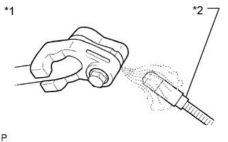
Text in Illustration *1 Check for Leakage *2 Halogen Leak Detector Using a halogen leak detector, check the refrigerant line for leakage.
-
If a gas leak is not detected from the drain hose, remove the blower motor control (blower resistor) from the cooling unit. Insert the halogen leak detector sensor into the unit and check for gas leakage.
-
Disconnect the pressure switch connector and wait for approximately 20 minutes. Bring the halogen leak detector close to the pressure switch and check for gas leakage.
-
-
INSTALL RADIATOR SUPPORT OPENING COVER
-
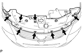
Install the radiator support opening cover with the 8 clips.
-
-
INSTALL ENGINE ROOM SIDE COVER
-
Install the engine room side cover with the clip.
-
-
INSTALL NO. 1 ENGINE COVER
-
for 1AD-FTV:
Install the No. 1 engine cover Click here.
-
for 2AD-FHV:
Install the No. 1 engine cover Click here.
-
for 2AD-FTV:
Install the No. 1 engine cover Click here.
-
-
INSTALL NO. 1 ENGINE UNDER COVER
-
for 1AD-FTV:
Install the No. 1 engine under cover Click here.
-
for 2AD-FHV:
Install the No. 1 engine under cover Click here.
-
for 2AD-FTV:
Install the No. 1 engine under cover Click here.
-
-
INSTALL FRONT LOWER BUMPER ABSORBER
-
Insert the 2 hooks of the front lower bumper absorber into the installation holes on the body to install the front lower bumper absorber.
-
Install the 8 bolts and 3 screws.
-
Install the 4 screws and 2 bolts.
-