AIR CONDITIONING UNIT (for Automatic Air Conditioning System) REMOVAL

Tech Tips
-
Use the same procedure for LHD and RHD vehicles.
-
The procedure listed below is for LHD vehicles.
-
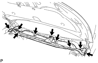
REMOVE FRONT BUMPER ABSORBER LOWER COVER
-
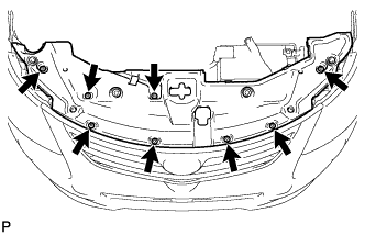
Remove the 4 screws and 2 bolts.
-
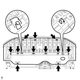
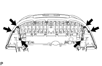
Remove the 8 bolts and 3 screws.
-
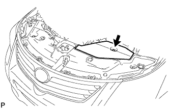
Detach the 2 hooks of the front lower bumper absorber from the installation holes on the body and remove the front lower bumper absorber.
-
-
REMOVE NO. 1 ENGINE UNDER COVER
-
for 1AD-FTV:
Remove the No. 1 engine under cover Click here.
-
for 2AD-FHV:
Remove the No. 1 engine under cover Click here.
-
for 2AD-FTV:
Remove the No. 1 engine under cover Click here.
-
-
REMOVE NO. 1 ENGINE COVER
-
for 1AD-FTV:
Remove the No. 1 engine cover Click here.
-
for 2AD-FHV:
Remove the No. 1 engine cover Click here.
-
for 2AD-FTV:
Remove the No. 1 engine cover Click here.
-
-
REMOVE ENGINE ROOM SIDE COVER
-
Remove the clip and engine room side cover.
-
-
REMOVE RADIATOR SUPPORT OPENING COVER
-
Remove the 8 clips and radiator support opening cover.
-
-
DRAIN ENGINE COOLANT
-
for 1AD-FTV:
Drain the engine coolant Click here.
-
for 2AD-FHV:
Drain the engine coolant Click here.
-
for 2AD-FTV:
Drain the engine coolant Click here.
-
-
RECOVER REFRIGERANT FROM REFRIGERATION SYSTEM
-
Start the engine.
-
Turn the A/C switch on.
-
Operate the cooler compressor while the engine speed is approximately 1000 rpm for 5 to 6 minutes to circulate the refrigerant and collect the compressor oil remaining in each component into the cooler compressor.
-
Stop the engine.
-
Recover the refrigerant from the A/C system using a refrigerant recovery unit.
-
-
DISCONNECT CABLE FROM NEGATIVE BATTERY TERMINAL
CAUTION:
Wait at least 90 seconds after disconnecting the cable from the negative (-) battery terminal to disable the SRS system.
Note
-
w/ Navigation System for HDD:
After the ignition switch is turned off, the HDD navigation system requires approximately a minute to record various types of memory and settings. As a result, after turning the ignition switch off, wait a minute or more before disconnecting the cable from the negative (-) battery terminal.
-
When disconnecting the cable, some systems need to be initialized after the cable is reconnected Click here.
-
-
REMOVE FRONT WIPER MOTOR AND BRACKET
-
Remove the front wiper motor and bracket Click here.
-
-
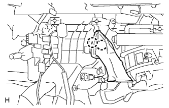
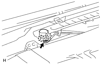
REMOVE DIFFERENTIAL PRESSURE SENSOR ASSEMBLY (for DPF)
-
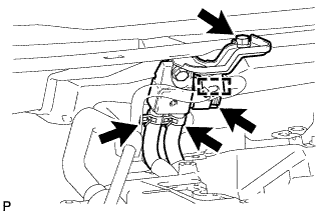
Detach the wire harness clamp and disconnect the sensor connector.
-
Remove the bolt and sensor.
-
Disconnect the 2 vacuum hoses.
-
-
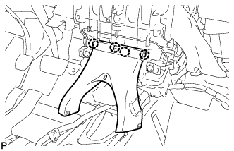
REMOVE COWL TOP OUTER PANEL
-
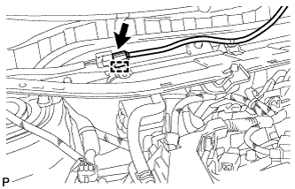
Disconnect the connector and detach the harness clamp.
-
Remove the 9 bolts and outer cowl top panel.
-
-
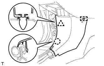
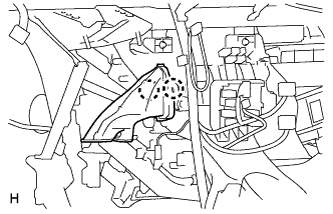
DISCONNECT AIR CONDITIONING TUBE ASSEMBLY
-
Remove the bolt.
-
Detach the plate as shown in the illustration.
-
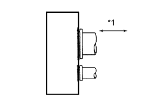
Text in Illustration *1 Disconnect tube by hand Disconnect the air conditioning tube assembly.
Note
-
Do not use a screwdriver or similar tool to disconnect the tube.
-
Seal the openings of the disconnected parts using vinyl tape to prevent moisture and foreign matter from entering them.
-
-
Remove the 2 O-rings from the air conditioning tube assembly.
-
-
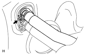
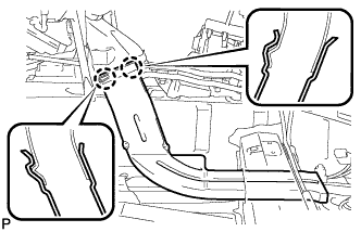
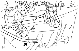
DISCONNECT HEATER WATER OUTLET HOSE A
-
Using pliers, grip the claws of the clip and slide the clip.
-
Disconnect the heater water outlet hose.
-
-
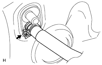
DISCONNECT HEATER WATER INLET HOSE A
-
Using pliers, grip the claws of the clip and slide the clip.
-
Disconnect the heater water inlet hose.
-
-
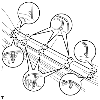
REMOVE FRONT DOOR SCUFF PLATE LH
-
Detach the 8 claws and 2 clips, and remove the front door scuff plate.
-
-
REMOVE FRONT DOOR SCUFF PLATE RH
Tech Tips
Use the same procedure described for the LH side.
-
REMOVE COWL SIDE TRIM BOARD LH
-
Detach the clip, claw and guide, and remove the cowl side trim board.
-
-
REMOVE COWL SIDE TRIM BOARD RH
Tech Tips
Use the same procedure described for the LH side.
-
REMOVE UPPER INSTRUMENT PANEL SUB-ASSEMBLY
-
Remove the upper instrument panel Click here.
-
-
REMOVE LOWER INSTRUMENT PANEL SUB-ASSEMBLY
-
Remove the lower instrument panel Click here.
-
-
REMOVE REAR NO. 3 AIR DUCT
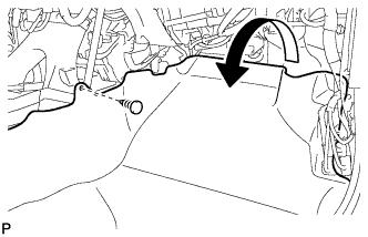
-
Remove the clip.
-
Fold back the floor carpet.
-
Detach the 2 claws and remove the rear No. 3 air duct.
-
-
REMOVE REAR NO. 2 AIR DUCT
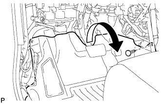
-
Remove the clip.
-
Fold back the floor carpet.
-
Detach the 2 claws and remove the rear No. 2 air duct.
-
-
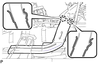
REMOVE REAR NO. 1 AIR DUCT
-
Detach the 4 claws and remove the rear No. 1 air duct.
-
-
REMOVE NO. 3 AIR DUCT SUB-ASSEMBLY (for Driver Side)
-
Detach the 2 claws and remove the duct.
-
-
REMOVE NO. 3 AIR DUCT SUB-ASSEMBLY (for Front Passenger Side)
-
Detach the 2 claws and remove the duct.
-
-
REMOVE STEERING COLUMN ASSEMBLY
-
for Manual Tilt and Manual Telescopic Steering Column:
Remove the steering column Click here.
-
for Power Tilt and Power Telescopic Steering Column:
Remove the steering column Click here.
-
-
REMOVE COOLER (SOLAR SENSOR) THERMISTOR
-
Disconnect the connector.
-
Detach the 2 claws and remove the sensor.
-
-
REMOVE DEFROSTER NOZZLE ASSEMBLY
-
w/ Navigation System:
Remove the navigation antenna assembly.
-
Remove the 2 screws.
-
Detach the claw and remove the navigation antenna assembly.
-
-
Detach the 4 claws and remove the defroster nozzle assembly.
-
-
REMOVE AIR DUCT ASSEMBLY
-
Remove the 2 nuts and duct.
-
-
REMOVE CENTER INSTRUMENT PANEL TO COWL BRACE
-
Remove the 2 bolts and brace.
-
-
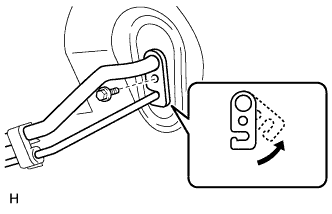
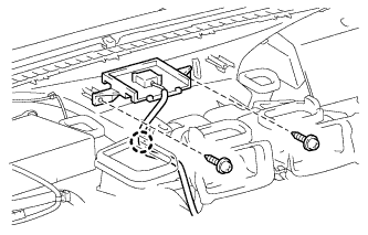
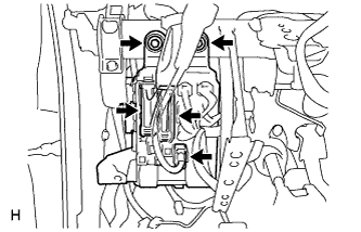
REMOVE POWER STEERING ECU ASSEMBLY
-
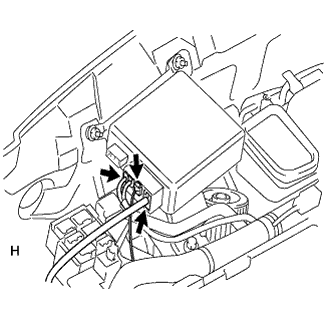
Detach the wire harness clamp from the power steering ECU.
-
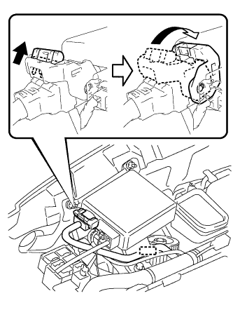
Disconnect the connector from the power steering ECU.
-
As shown in the illustration, pull out the lock of the lock lever and turn the lock lever to disconnect the connector.
-
-
Disconnect the 3 connectors from the power steering ECU.
-
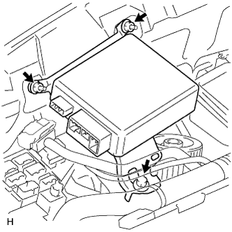
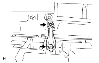
Remove the bolt, 2 nuts and power steering ECU.
-
-
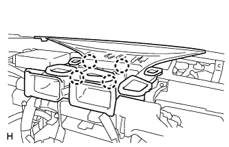
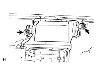
REMOVE MAIN BODY ECU (INSTRUMENT PANEL JUNCTION BLOCK ASSEMBLY)
-
Disconnect the 3 connectors.
-
Remove the 2 bolts and main body ECU.
-
-
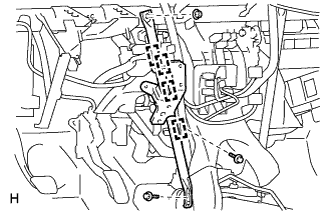
REMOVE NO. 1 INSTRUMENT PANEL BRACE SUB-ASSEMBLY
-
Detach the 4 clamps.
-
Remove the nut, 2 bolts and brace.
-
-
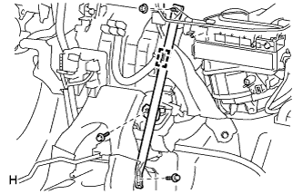
REMOVE NO. 2 INSTRUMENT PANEL BRACE SUB-ASSEMBLY
-
Detach the clamp.
-
Remove the nut, 2 bolts and brace.
-
-
REMOVE INSTRUMENT PANEL REINFORCEMENT ASSEMBLY
-
Disconnect the clamps, connectors and wire harness.
-
Remove the instrument panel reinforcement.
-
for Manual Transaxle:
Remove the bolt from the clutch pedal.
-
Remove the bolts, screws and instrument panel reinforcement.
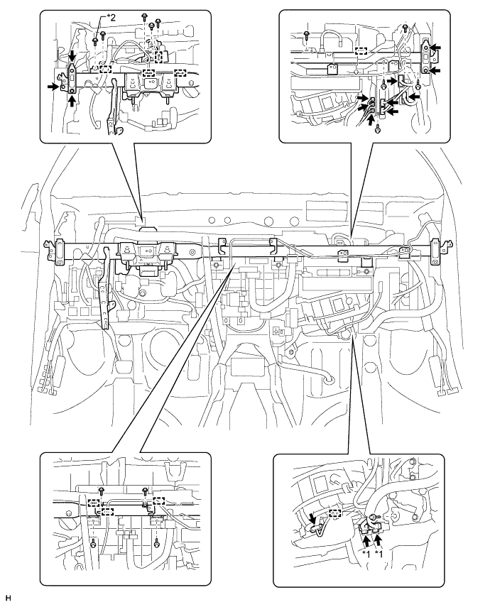
Text in Illustration *1 w/ PTC Heater *2 for Manual Transaxle
-
-
-
REMOVE AIR CONDITIONING UNIT
-
Disconnect the drain cooler hose.
-
Remove the nut, bolt and air conditioning unit.
-