ENGINE OIL COOLER REMOVAL

Note
-
When replacing the injectors (including shuffling the injectors between the cylinders), common rail, intake manifold or cylinder head, it is necessary to replace the injection pipes with new ones.
-
When replacing the fuel supply pump, common rail, intake manifold or cylinder head, it is necessary to replace the fuel inlet pipe with a new one.
-
REMOVE NO. 1 ENGINE COVER
-
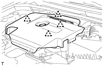
Hold the rear of the cover and slowly raise it to detach the clip on the rear of the cover. Continue to raise the cover to detach the 3 clips on the front and side of the cover and remove the cover.
Note
Attempting to disengage both front and rear clips at the same time may cause the cover to break.
-
-
REMOVE ENGINE ROOM SIDE COVER
-
Remove the clip and engine room side cover.
-
-
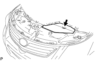
REMOVE RADIATOR SUPPORT OPENING COVER
-
Remove the 8 clips and radiator support opening cover.
-
-
DISCONNECT CABLE FROM NEGATIVE BATTERY TERMINAL
Note
-
When disconnecting the cable, some systems need to be initialized after the cable is reconnected Click here.
-
w/ Navigation System (for HDD):
After the ignition switch is turned off, the HDD navigation system requires approximately a minute to record various types of memory and settings. As a result, after turning the ignition switch off, wait a minute or more before disconnecting the cable from the negative (-) battery terminal.
-
-
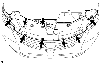
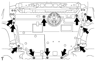
REMOVE FRONT LOWER BUMPER ABSORBER
-
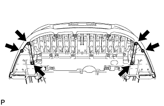
Remove the 4 screws and 2 bolts.
-
Remove the 8 bolts and 3 screws.
-
Detach the 2 hooks of the front lower bumper absorber from the installation holes on the body and remove the front lower bumper absorber.
-
-
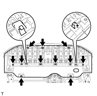
REMOVE ENGINE UNDER COVER
-
Remove the 11 clips and engine under cover.
-
-
DRAIN ENGINE OIL
-
Remove the oil filler cap.
-
Remove the oil pan drain plug and gasket, and then drain the engine oil into a container.
-
Install a new gasket and the oil pan drain plug.
- Torque:
- 38 N*m { 387 kgf*cm, 28 ft.*lbf }
-
-
DRAIN ENGINE COOLANT
-
Loosen the radiator drain cock plug.
Tech Tips
Collect the coolant in a container and dispose of it according to the regulations in your area.
-
Remove the radiator reservoir cap.
CAUTION:
Do not remove the radiator reservoir cap and air release plug while the engine and radiator are still hot. Pressurized, hot engine coolant and steam may be released and cause serious burns.
-
Loosen the cylinder block drain cock plug. Then drain the coolant from the engine.
Tech Tips
The plug is on the backside of the generator on the EGR cooler side.
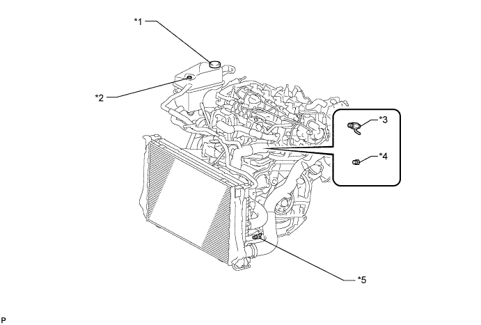
Text in Illustration *1 Radiator Reservoir Cap *2 Air Release Plug *3 Cylinder Block Drain Cock Plug (Type A) *4 Cylinder Block Drain Cock Plug (Type B) *5 Radiator Drain Cock Plug - -
-
-
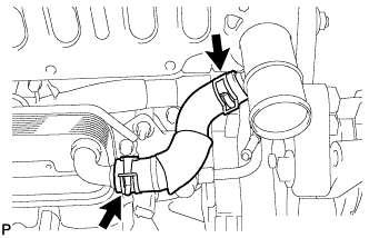
REMOVE NO. 3 AIR HOSE
-
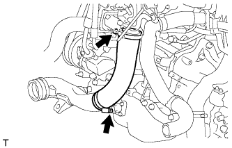
Loosen the 2 hose clamps.
-
Remove the No. 3 air hose from the No. 2 air tube and diesel throttle body.
-
-
REMOVE DIESEL THROTTLE BODY ASSEMBLY
-
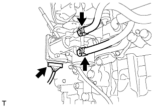
Disconnect the No. 7 water by-pass hose from the throttle body.
-
Disconnect the No. 6 water by-pass hose from the throttle body.
-
Disconnect the throttle position sensor and throttle motor connector.
-
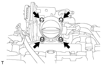
Remove the 2 nuts, 2 bolts, diesel throttle body and gasket.
-
-
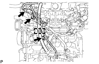
DISCONNECT ENGINE WIRE
-
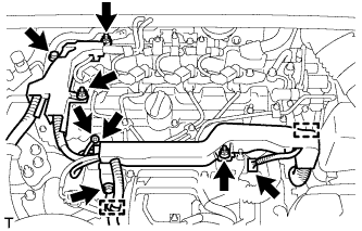
Disconnect the fuel pressure sensor connector.
-
Disconnect the pressure discharge valve connector.
-
Remove the grommet and nut, and disconnect the glow plug wire harness.
-
Detach the 2 wire harness clamps.
-
Remove the bolt and wire harness bracket.
-
Remove the bolt and 3 nuts, and disconnect the engine wire.
-
-
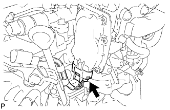
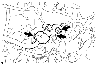
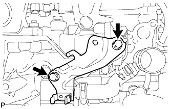
REMOVE EGR VALVE BRACKET
-
Disconnect the 2 connectors and detach the 2 wire harness clamps.
-
Remove the 3 bolts and 2 EGR valve brackets.
-
-
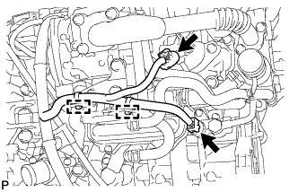
REMOVE NO. 7 WATER BY-PASS HOSE
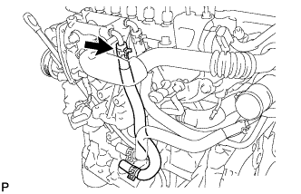
-
DISCONNECT NO. 8 WATER BY-PASS HOSE
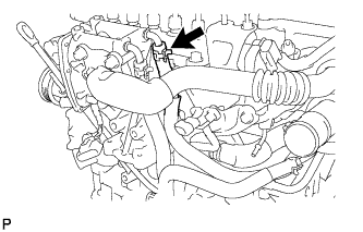
-
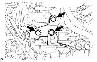
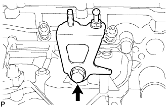
REMOVE NO. 2 EGR PIPE SUB-ASSEMBLY
-
Disconnect the electric EGR control valve connector.
-
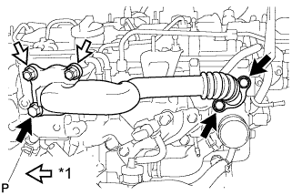
Text in Illustration *1 Nut Remove the 3 bolts, 2 nuts and No. 2 EGR pipe.
-
Remove the 2 gaskets.
-
-
REMOVE ELECTRIC EGR CONTROL VALVE ASSEMBLY
-
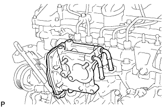
Remove the electric EGR control valve and gasket.
-
-
REMOVE FUEL INLET PIPE SUB-ASSEMBLY
Note
After removing the fuel inlet pipe, cover the common rail and supply pump with electrical tape to prevent dirt from entering them.
-
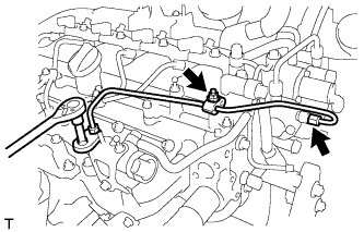
Remove the nut and 2 clamps.
-
Using a 14 mm union nut wrench, remove the fuel inlet pipe.
-
-
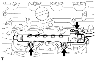
REMOVE INJECTION PIPE SUB-ASSEMBLY
Note
After removing the injection pipe, to prevent dirt or foreign objects from entering the pipe inlet, cover the common rail with electrical tape. Also protect the injector inlets with electrical tape or plastic bags.
-

Remove the 2 bolts and 4 injection pipe clamps.
-
Using a 14 mm union nut wrench, loosen the 4 nuts at the common rail end of the injection pipes.
-
Using a 14 mm union nut wrench, loosen the 4 nuts at the injector end of the injection pipes.
-
Remove the 4 injection pipes.
-
-
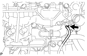
REMOVE COMMON RAIL ASSEMBLY
-
Using pliers, grip the claws of the clip and slide the clip to disconnect the fuel hose.
-
Remove the 2 bolts and common rail.
-
-
REMOVE INTAKE MANIFOLD INSULATOR
-
Remove the intake manifold insulator from the intake manifold.
-
-
REMOVE ENGINE OIL LEVEL DIPSTICK GUIDE
-
Remove the engine oil level dipstick.
-
Disconnect the connector and detach the wire harness clamp from the engine oil level dipstick guide.
-
Remove the 2 bolts and engine oil level dipstick guide.
-
Remove the O-ring from the engine oil level dipstick guide.
-
-
REMOVE DIESEL TURBO PRESSURE SENSOR
-
Disconnect the vacuum hose.
-
Disconnect the sensor connector.
-
Remove the bolt and sensor.
-
-
REMOVE NO. 1 GAS FILTER
-
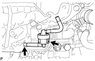
Disconnect the vacuum hose.
-
Remove the No. 1 gas filter from the gas filter bracket.
-
-
REMOVE GAS FILTER BRACKET
-
Remove the 2 bolts and gas filter bracket.
-
-
REMOVE ENGINE COVER BRACKET
-
Remove the bolt and engine cover bracket.
-
-
REMOVE NO. 2 INTAKE MANIFOLD
-
Remove the bolt, 2 nuts, No. 2 intake manifold and gasket.
-
-
DISCONNECT NO. 2 VACUUM TRANSMITTING HOSE
-
Disconnect the No. 2 vacuum transmitting hose from the intake manifold.
-
-
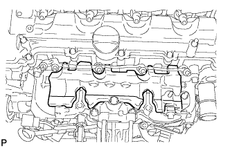
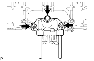
REMOVE INTAKE MANIFOLD
-
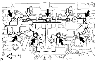
Text in Illustration *1 Nut Remove the 7 bolts, 2 nuts, intake manifold and gasket.
-
Remove the gasket from the cylinder head.
-
-
REMOVE WATER BY-PASS HOSE
-
REMOVE OIL COOLER ASSEMBLY
-
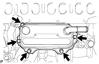
Remove the 5 bolts and oil cooler.
-
Remove the 3 O-rings from the oil cooler bracket.
-