RADIATOR (for Automatic Transaxle) INSTALLATION

-
INSTALL FAN SHROUD
-
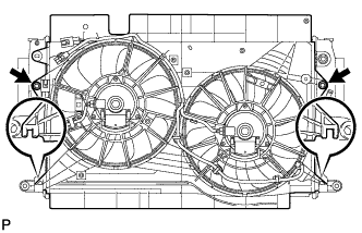
Insert the fan shroud hooks into the radiator holes and install the fan shroud with the 2 bolts.
- Torque:
- 7.0 N*m { 71 kgf*cm, 62 in.*lbf }
-
-
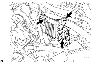
INSTALL INTERCOOLER ASSEMBLY (for Automatic Transaxle)
-
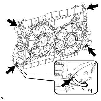
Text in Illustration *1 No. 1 Vacuum Transmitting Hose Install the intercooler with the 4 bolts.
- Torque:
- 7.0 N*m { 71 kgf*cm, 62 in.*lbf }
-
Connect the No. 1 vacuum transmitting hose to the intercooler.
-
-
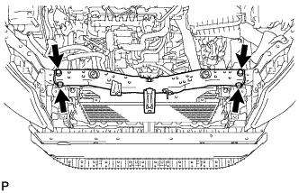
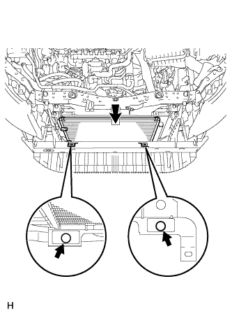
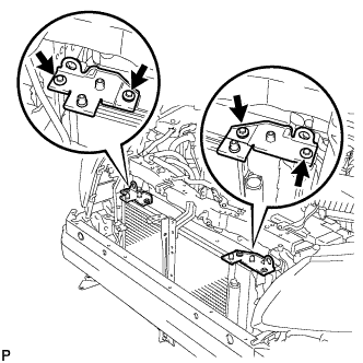
INSTALL LOWER RADIATOR SUPPORT SUB-ASSEMBLY
-
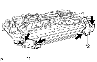
Text in Illustration *1 Lower Radiator Support LH *2 Lower Radiator Support RH Install the lower radiator support RH with the 2 bolts.
- Torque:
- 7.0 N*m { 71 kgf*cm, 62 in.*lbf }
-
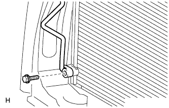
Attach the clamp to the vacuum transmitting pipe, and then install the lower radiator support LH with the 2 bolts.
- Torque:
- 7.0 N*m { 71 kgf*cm, 62 in.*lbf }
-
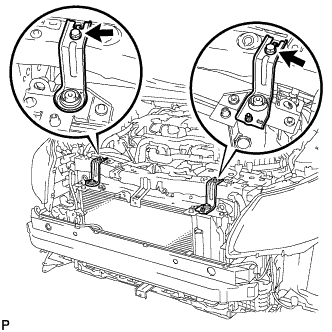
-
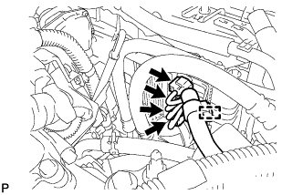
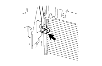
INSTALL NO. 1 VACUUM TRANSMITTING PIPE SUB-ASSEMBLY (for Automatic Transaxle)
-
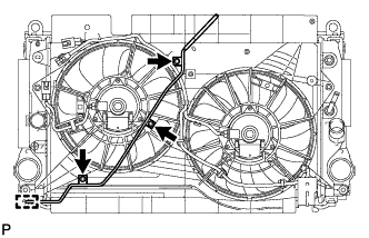
Attach the clamp to the lower radiator support.
-
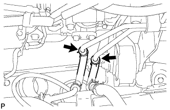
Install the No. 1 vacuum transmitting pipe with the 3 bolts.
- Torque:
- 7.0 N*m { 71 kgf*cm, 62 in.*lbf }
-
-
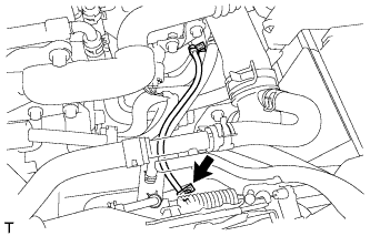
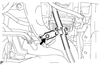
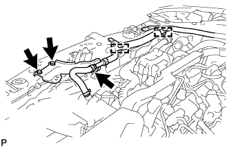
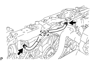
INSTALL OIL COOLER HOSE TUBE SUB-ASSEMBLY
-
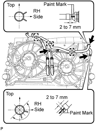
Connect the 2 hoses of the oil cooler hose tube to the radiator and attach the 2 clips.
Tech Tips
-
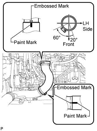
Position the clips and align the paint marks as illustrated.
-
Position the clips so that the distance from the end of the hose is 2 to 7 mm (0.0787 to 0.275 in.).
-
-
Attach the 3 clamps and install the oil cooler hose tube with the bolt.
- Torque:
- 5.5 N*m { 56 kgf*cm, 49 in.*lbf }
-
-
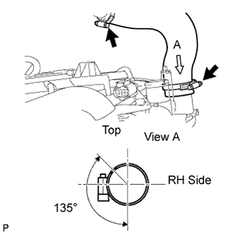
INSTALL NO. 2 AIR TUBE
-
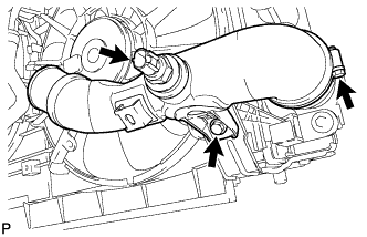
Install the No. 2 air tube with the bolt.
Note
Before installation, remove any oil residue from the inside of the pipe and hose.
- Torque:
- 31 N*m { 316 kgf*cm, 23 ft.*lbf }
-
Tighten the hose clamp.
- Torque:
- 6.5 N*m { 66 kgf*cm, 58 in.*lbf }
-
Connect the air temperature sensor connector.
-
-
INSTALL RADIATOR ASSEMBLY
-
Install the 2 radiator lower support cushions.
-
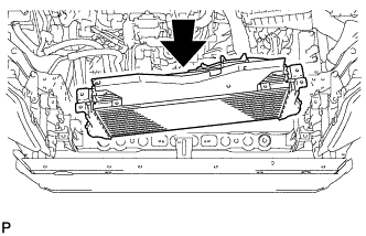
Insert the radiator with intercooler while holding it at an angle to install it as shown in the illustration.
Note
Do not apply any excessive force to the cooler pipe when installing the radiator assembly.
-
Connect the No. 2 vacuum transmitting hose.
-
Connect the 2 oil cooler hoses and attach the 2 clips.
-
-
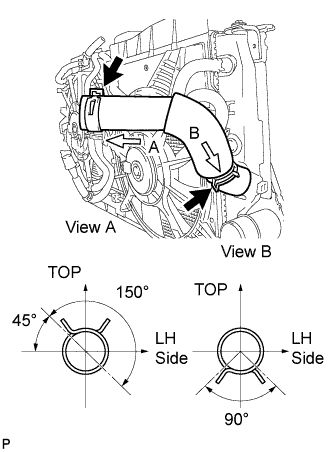
INSTALL NO. 3 AIR HOSE
Note
Before installation, remove any oil residue from the inside of the throttle body and tube.
-
Align the paint mark of the No. 3 air hose with the embossed mark of the throttle body.
-
Align the paint mark of the No. 3 air hose with the embossed mark of the No. 2 air tube.
-
Tighten the clamp of the No. 3 air hose on the diesel throttle body side.
- Torque:
- 6.5 N*m { 66 kgf*cm, 58 in.*lbf }
Tech Tips
-
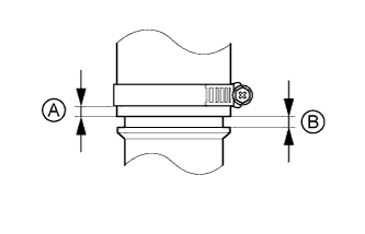
Align the paint mark of the air hose with the embossed mark and push in the air hose so that distance B is 0 to 2 mm (0 to 0.0787 in.).
-
Position the clamp so that distance A is 4 to 9 mm (0.157 to 0.354 in.).
-
Tighten the clamp of the No. 3 air hose on the No. 2 air tube side.
- Torque:
- 6.5 N*m { 66 kgf*cm, 58 in.*lbf }
Tech Tips
-
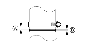
Align the paint mark of the air hose with the embossed mark and push in the air hose so that distance B is 0 to 2 mm (0 to 0.0787 in.).
-
Position the clamp so that distance A is 9 to 15 mm (0.354 to 0.591 in.).
-
-
INSTALL INTERCOOLER AIR HOSE
Note
Before installation, remove any oil residue from the inside of the tube.
-
Install the intercooler air hose to the No. 1 air tube and intercooler and tighten the hose clamps.
- Torque:
- 6.5 N*m { 66 kgf*cm, 58 in.*lbf }
-
Install the wire harness clamp with the bolt.
- Torque:
- 8.4 N*m { 85 kgf*cm, 74 in.*lbf }
-
Attach the clamp.
-
-
INSTALL NO. 2 RADIATOR HOSE
-
Connect the No. 2 radiator hose.
Tech Tips
Position the clips as illustrated.
-
-
INSTALL NO. 1 RADIATOR HOSE
-
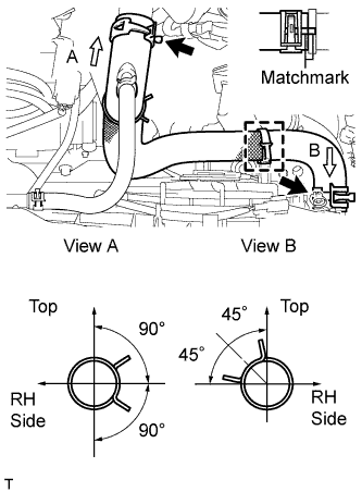
Connect the No. 1 radiator hose.
Tech Tips
Position clips A and B as Illustrated.
-
-
INSTALL HOOD LOCK SUPPORT SUB-ASSEMBLY
-
Install the hood lock support sub-assembly with the 4 bolts.
- Torque:
- 13 N*m { 127 kgf*cm, 9 ft.*lbf }
-
-
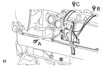
INSTALL HOOD LOCK ASSEMBLY
-
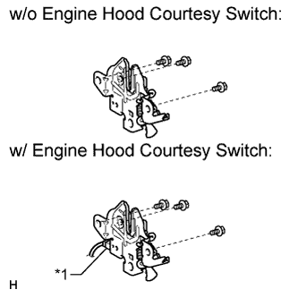
Text in Illustration *1 Engine Hood Courtesy Switch Install the hood lock with the 3 bolts.
- Torque:
- 7.5 N*m { 76 kgf*cm, 66 in.*lbf }
-
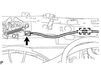
Connect the hood lock control cable.
-
w/ Engine Hood Courtesy Switch:
Attach the clamp and connect the hood lock courtesy switch connector.
-
-
INSTALL INJECTOR DRIVER
-
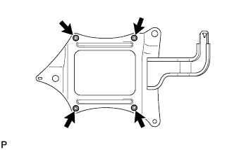
Install the injector driver bracket with the 4 screws.
- Torque:
- 2.0 N*m { 20 kgf*cm, 18 in.*lbf }
-
Install the injector driver with the 3 bolts.
- Torque:
- 6.0 N*m { 61 kgf*cm, 53 in.*lbf }
-
Attach the clamp and connect the 4 connectors.
-
-
CONNECT NO. 1 WATER HOSE CLAMP BRACKET
-
Connect the No. 1 water hose clamp bracket to the radiator support with the 2 bolts.
- Torque:
- 5.0 N*m { 51 kgf*cm, 44 in.*lbf }
-
Attach the 2 hose clamps to the No. 2 by-pass water hose, and then connect the No. 1 radiator hose to the No. 1 water hose clamp bracket.
-
-
INSTALL NO. 3 WATER BY-PASS HOSE
-
Connect the 3 connectors and attach the clamp.
-
Install the No. 3 water by-pass hose and attach the clamp.
-
-
INSTALL CONDENSER ASSEMBLY WITH RECEIVER
-
Install the condenser assembly with receiver as shown in the illustration.
Tech Tips
If the condenser is replaced with a new one, add compressor oil to a new condenser.
Capacity 40 cc (1.4 fl.oz) Compressor oil ND-OIL 8 or equivalent
-
-
CONNECT SUCTION PIPE SUB-ASSEMBLY
-
Remove the attached vinyl tape from the pipe and the connecting part of the cooler condenser assembly.
-
Sufficiently apply compressor oil to a new O-ring and the fitting surface of the pipe joint.
Compressor oil ND-OIL 8 or equivalent -
Install the O-ring to the suction pipe sub-accessory assembly.
-
Connect the suction pipe sub-assembly to the cooler condenser assembly with the bolt.
- Torque:
- 5.4 N*m { 55 kgf*cm, 48 in.*lbf }
-
-
CONNECT DISCHARGE HOSE SUB-ASSEMBLY
-
Remove the attached vinyl tape from the hose and the connecting part of the cooler condenser assembly.
-
Sufficiently apply compressor oil to a new O-ring and the fitting surface of the hose joint.
Compressor oil ND-OIL 8 or equivalent -
Install the O-ring to the discharge hose sub-assembly.
-
Connect the discharge hose sub-assembly to the cooler condenser assembly with the bolt.
- Torque:
- 5.4 N*m { 55 kgf*cm, 48 in.*lbf }
-
-
INSTALL UPPER RADIATOR SUPPORT SUB-ASSEMBLY
-
Install the 2 upper radiator supports with the 4 bolts.
- Torque:
- 7.0 N*m { 71 kgf*cm, 62 in.*lbf }
-
Install the 2 radiator support cushions.
-
-
INSTALL UPPER RADIATOR SUPPORT
-
Install the 2 upper radiator supports with the 2 bolts.
- Torque:
- 19 N*m { 194 kgf*cm, 14 ft.*lbf }
-
-
INSTALL RADIATOR SIDE DEFLECTOR LH
-
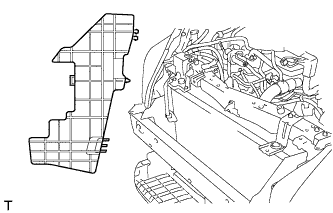
Install the radiator side deflector LH.
-
-
INSTALL RADIATOR SIDE DEFLECTOR RH
-
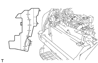
Install the radiator side deflector RH.
-
-
CONNECT AMBIENT THERMISTOR ASSEMBLY
-
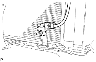
Attach the clamp to connect the ambient thermistor.
-
-
INSTALL HORN ASSEMBLY
-
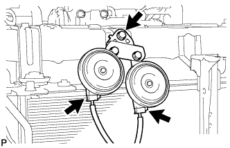
Install the horn with the bolt.
- Torque:
- 20 N*m { 199 kgf*cm, 14 ft.*lbf }
-
Connect the 2 horn connectors.
-
-
INSTALL RADIATOR GRILLE BRACKET
-
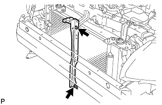
Install the radiator grille bracket with the bolt and nut.
- Torque:
- 13 N*m { 127 kgf*cm, 9 ft.*lbf }
-
-
INSTALL OIL COOLER ASSEMBLY
-
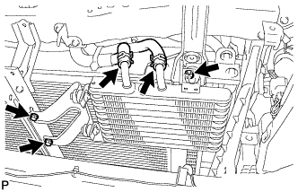
Install the oil cooler with the 2 bolts and nut.
- Torque:
- 5.5 N*m { 56 kgf*cm, 49 in.*lbf }
-
Connect the 2 oil cooler hoses and attach the 2 clips.
-
-
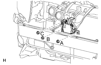
INSTALL NO. 1 MILLIMETER WAVE RADAR SENSOR BRACKET (w/ Dynamic Radar Cruise Control System)
-
Install the bracket with the 3 bolts in the alphabetical order.
- Torque:
- 5.5 N*m { 56 kgf*cm, 49 in.*lbf }
-
Install the nut.
- Torque:
- 5.5 N*m { 56 kgf*cm, 49 in.*lbf }
-
-
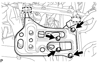
INSTALL MILLIMETER WAVE RADAR SENSOR ASSEMBLY (w/ Dynamic Radar Cruise Control System)
-
Install the sensor with the 3 nuts in the alphabetical order.
- Torque:
- 5.5 N*m { 56 kgf*cm, 49 in.*lbf }
-
Connect the sensor connector.
-
-
INSTALL BATTERY CARRIER
-
Install the battery carrier with the 4 bolts.
- Torque:
- 19 N*m { 189 kgf*cm, 14 ft.*lbf }
-
Attach the 2 clamps to connect the wire harness.
-
-
INSTALL BATTERY TRAY
-
INSTALL BATTERY
-
INSTALL BATTERY INSULATOR
-
INSTALL BATTERY CLAMP SUB-ASSEMBLY
-
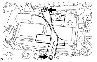
Attach the hook of the battery clamp to the battery carrier.
-
Partially tighten the nut and temporarily install the bolt.
-
Adjust the battery clamp position.
-
Tighten the nut and bolt.
- Torque:
- for bolt
- 17 N*m { 168 kgf*cm, 12 ft.*lbf }
- for nut
- 3.5 N*m { 36 kgf*cm, 31 in.*lbf }
-
-
CONNECT CABLE TO POSITIVE BATTERY TERMINAL
-
CONNECT CABLE TO NEGATIVE BATTERY TERMINAL
Note
When disconnecting the cable, some systems need to be initialized after the cable is reconnected Click here.
-
ADD ENGINE COOLANT
-
Tighten the radiator drain cock plug by hand.
-
Tighten the cylinder block drain cock plug.
- Torque:
- for Type A
- 13 N*m { 130 kgf*cm, 9 ft.*lbf }
- for Type B
- 25 N*m { 255 kgf*cm, 18 ft.*lbf }
-
Add TOYOTA Super Long Life Coolant (SLLC) to the radiator reservoir filler opening.
Standard Capacity Item Specified Condition w/o Power Heater 7.4 liters (7.8 US qts, 6.5 Imp. qts) w/ Power Heater 7.8 liters (8.2 US qts, 6.9 Imp. qts) Tech Tips
TOYOTA vehicles are filled with TOYOTA SLLC at the factory. In order to avoid damage to the engine cooling system and other technical problems, only use TOYOTA SLLC or similar high quality ethylene glycol based non-silicate, non-amine, non-nitrite, non-borate coolant with long-life hybrid organic acid technology (coolant with long-life hybrid organic acid technology is a combination of low phosphates and organic acids).
Note
Never use water as a substitute for engine coolant.
-
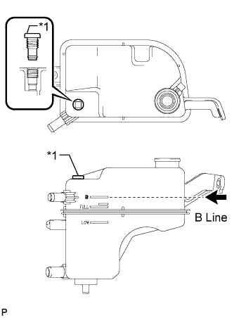
Text in Illustration *1 Air Release Plug Remove the radiator cap and air release plug and add coolant to the B line of the reservoir tank.
-
Squeeze the inlet and outlet radiator hoses several times by hand, and then check the level of the coolant.
If the coolant level is low, add coolant.
-
Install the cap and air release plug, and warm up the engine sufficiently.
- Torque:
- 2.0 N*m { 20 kgf*cm, 18 in.*lbf }
-
Bleed air from the cooling system.
Note
-
Before starting the engine, turn the A/C switch off.
-
Adjust the air conditioning temperature setting to MAX (HOT).
-
Adjust the air conditioning blower setting to Lo.
-
Warm up the engine until the thermostat opens. While the thermostat is open, allow the coolant to circulate for several minutes.
Tech Tips
The thermostat opening timing can be confirmed by squeezing the inlet radiator hose by hand and sensing vibrations when the engine coolant starts to flow inside the hose.
CAUTION:
When squeezing the radiator hoses:
-
Wear protective gloves.
-
Be careful as the radiator hoses are hot.
-
Keep your hands away from the radiator fan.
-
-
After the engine has warmed up, run the engine according to the following pattern for at least 7 minutes: 3000 rpm for 5 seconds, and then idle speed for 45 seconds (repeat this pattern at least 8 times).
-
Squeeze the inlet and outlet radiator hoses several times by hand to bleed air from the system.
CAUTION:
When squeezing the radiator hoses:
-
Wear protective gloves.
-
Be careful as the radiator hoses are hot.
-
Keep your hands away from the radiator fan.
-
-
-
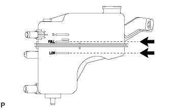
After the engine has cooled down, check that the coolant level is between FULL and LOW.
If the coolant level is low, add coolant until the coolant level reaches the reservoir tank FULL line.
-
-
CHARGE REFRIGERANT
- SST
- 09985-20010 ( 09985-02130, 09985-02150, 09985-02090, 09985-02110, 09985-02010, 09985-02050, 09985-02060, 09985-02070 )
-
Perform vacuum purging using a vacuum pump.
-
Charge refrigerant HFC-134a (R134a).
Standard 440 +/-30 g (15.5 +/-1.1 oz) 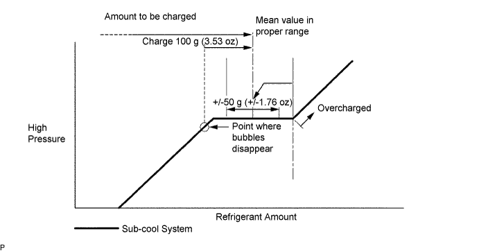
Note
-
Do not operate the cooler compressor before charging refrigerant as the cooler compressor will not work properly without any refrigerant, and will overheat.
-
Approximately 200 g (7.05 oz) of refrigerant may need to be charged after bubbles disappear. The refrigerant amount should be checked by measuring its quantity, and not with the sight glass.
-
-
WARM UP ENGINE
-
Warm up the engine at less than 1850 rpm for 2 minutes or more after charging the refrigerant.
Note
Be sure to warm up the compressor when turning the A/C switch on after removing and installing the cooler refrigerant lines (including the compressor) to prevent damage to the compressor.
-
-
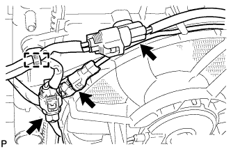
INSPECT FOR REFRIGERANT LEAK
-
After recharging the refrigerant gas, check for refrigerant gas leakage using a halogen leak detector.
-
Perform the operation observing the following instructions:
-
Stop the engine.
-
Secure good ventilation (the halogen leak detector may react to volatile gases other than refrigerant, such as evaporated gasoline or exhaust gas).
-
Repeat the test 2 or 3 times.
-
Make sure that some refrigerant remains in the refrigeration system.
Tech Tips
When the compressor is off: approximately 392 to 588 kPa (4.0 to 6.0 kgf/cm2, 57 to 85 psi).
-
-
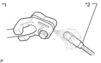
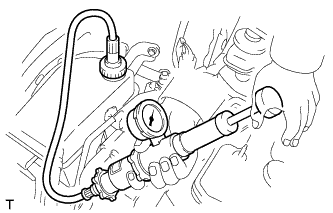
Text in Illustration *1 Check for Leakage *2 Halogen Leak Detector Using a halogen leak detector, check the refrigerant line for leakage.
-
If a gas leak is not detected from the drain hose, remove the blower motor control (blower resistor) from the cooling unit. Insert the halogen leak detector sensor into the unit and check for gas leakage.
-
Disconnect the pressure switch connector and wait for approximately 20 minutes. Bring the halogen leak detector close to the pressure switch and check for gas leakage.
-
-
ADJUSTMENT AUTOMATIC TRANSAXLE FLUID
-
Adjustment automatic transaxle fluid Click here.
-
-
INSPECT FOR COOLANT LEAK
-
Remove the radiator reservoir cap.
CAUTION:
To avoid the danger of being burned, do not remove the radiator reservoir cap while the engine and radiator are still hot. Thermal expansion will cause hot engine coolant and steam to blow out from the radiator.
-
Fill the radiator with coolant, and then attach a radiator cap tester.
-
Warm up the engine.
-
Pump the radiator cap tester to 118 kPa (1.2 kgf/cm2, 17 psi), and then check that the pressure does not drop.
If the pressure drops, check the hoses, radiator and water pump for leakage.
If there are no signs of external coolant leaks, check the heater core, cylinder block and head.
-
Reinstall the radiator reservoir cap.
-
-
ADJUST MILLIMETER WAVE RADAR SENSOR ASSEMBLY (w/ Dynamic Radar Cruise Control System)
CAUTION:
Exposure to radio frequency emissions is hazardous to your health. It is hazardous to be within 20 cm (7.87 in.) of the device's radio frequency aperture.
Note
-
This device complies with FCC radio frequency emission regulations.
-
Perform adjustment on a level surface.
-
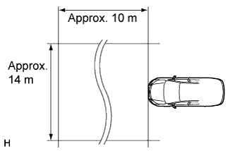
Make sure that no large pieces of metal are within a 10 m (32.81 ft.) x 14 m (45.93 ft.) area in front of the vehicle. If possible, the surrounding area should also be free of large metal objects.
-
Before adjusting the radar beam axis, prepare the vehicle as follows.
-
Check the tire pressure and adjust it if necessary.
-
Remove all excess weight from the vehicle (luggage, heavy objects, etc.).
-
-
Check and adjust the vertical direction of the radar sensor.
-
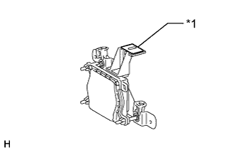
Text in Illustration *1 Level Remove dust, oil and foreign matter from the radar sensor's level rack.
-
Set a level on the radar sensor's level rack.
-
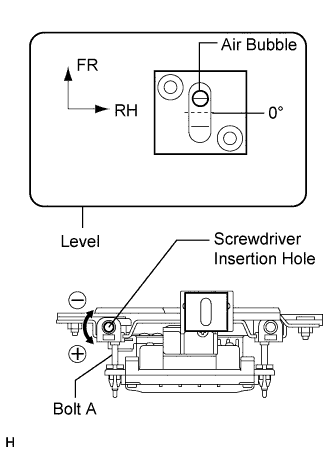
Check that the level's air bubble is within the red frame.
OK Level's air bubble is within red frame. If the bubble is not within the red frame, use a screwdriver to adjust bolt A until the level's air bubble is within the red frame.
Tech Tips
-
The adjustable range within the red frame of the level is +/-0.2°.
-
The target angle is +0.2° (upward angle of 0.2°).
Result Adjustment Direction Adjustment Procedure Adjustment Angle Vertical adjustment Upward direction: Turn bolt A to positive (+) side For every 8.6 rotations of adjustment bolt, sensor moves about 1° Downward direction: Turn bolt A to negative (-) side -
-
-
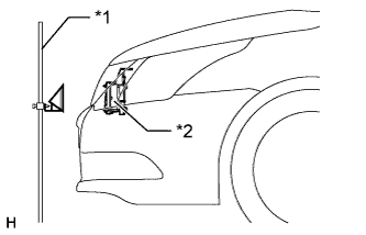
Text in Illustration *1 SST *2 Millimeter Wave Radar Sensor Assembly Adjust the reflector height.
-
Adjust the reflector so that the center of SST reflector is the same height as the millimeter wave radar sensor.
- SST
- 09870-60000 ( 09870-60010 )
- 09870-60040
Tech Tips
Prepare a 10 m (32.81 ft.) string, a string with a sharp-pointed weight (plumb bob), and a 5 m (16.41 ft.) tape measure.
-
-
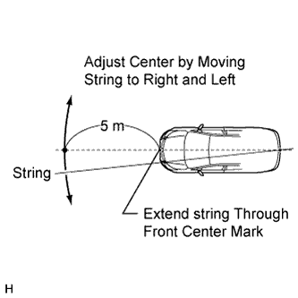
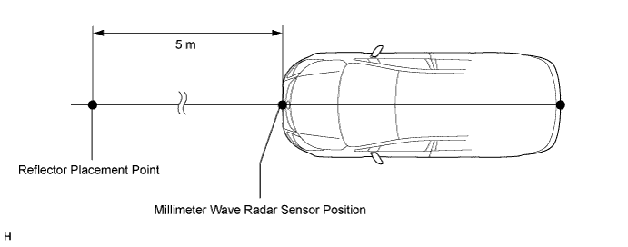
Place the reflector.
-
Hang the string (with weight) from the center of the vehicle rear's emblem. Mark the vehicle rear's center point on the ground. Repeat for the front of the vehicle.
-
Set one end of the more than 10 m (32.81 ft.) string on the vehicle rear's center point. Run the string over the vehicle front's center point to a position 5 m (16.4 ft.) beyond the vehicle front's center point, as shown in the illustration. Mark the 5 m (16.4 ft.) position.
-
Place the reflector (SST) at the marked position.
Note
Perform the operation as precisely as possible.
-
-
Check the radar beam axis.
Tech Tips
If a screen indicating an error is displayed while performing this procedure, perform the procedure again from *1.
-
Connect the intelligent tester to the DLC3.
-
Turn the engine switch on (IG).
-
Turn the intelligent tester main switch on, and turn the cruise control main switch on.
-
Select "Auto" from the intelligent tester display screen. *1
-
Select "Radar Cruise" from the display screen.
-
Select the appropriate menu item.
-
For vehicles with lane recognition camera: select "w/ LKA System" from the display screen.
-
For vehicles without lane recognition camera: select "w/o LKA System" from the display screen.
-
-
Select "Radar Cruise" from the display screen.
-
Select "Utility" from the display screen.
-
Select "Beam Axis Adjustment" from the display screen.
-
Follow the tester display, and select "Next".
Note
-
Turn the cruise control main switch ON before pressing Next.
-
Make sure there is at least 20 cm (7.9 in.) between the radar sensor and any nearby individuals.
CAUTION:
Do not come within 20 cm (7.9 in.) of the radar sensor.
-
-
Check the following items on the radar cruise divergence data screen.
CAUTION:
While using the intelligent tester's beam axis adjustment mode, the actual direction and angle of the radar sensor may be different from the intelligent tester's data. In such a case, the deviation is displayed on the combination meter's multi-information display.
-
Confirm that the distance value is approximately 5 m (16.4 ft.).
Tech Tips
-
A value between 0.0 and 6.3 m (20.67 ft.) is indicated.
-
If the distance is 0 m (0 ft.), the sensor cannot detect the target. Reconfirm that there is no metal in the specified area in front of the vehicle (refer to the NOTICE at the beginning of this adjustment procedure).
-
-
Confirm that the left/right side value is between 0.0 and 6.3.
Tech Tips
If the distance is 0 m (0 ft.), the sensor cannot detect the target. Reconfirm that there is no metal in the specified area in front of the vehicle (refer to the NOTICE at the beginning of this adjustment procedure).
-
-
-
Check and adjust the horizontal direction of the radar sensor.
-
Check that the divergence of the radar beam axis is 0°.
Standard 0° (Both right and left) If the axis is not as specified, use a screwdriver to adjust bolt B until the divergence of the radar beam axis is 0°.
-
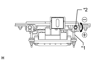
Text in Illustration *1 Bolt B *2 Screwdriver Insertion Hole Based on the measured divergence of the beam axis, turn and adjust bolt B for horizontal adjustment of the millimeter wave radar sensor using a screwdriver.
Result Adjustment Direction Adjustment Procedure Adjustment Angle Horizontal adjustment Right direction: Turn bolt B to positive (+) side. For every 14.8 rotations of adjustment bolt, sensor moves about 1° Left direction: Turn bolt B to negative (-) side. Tech Tips
-
If "LEFT SIDE: 1.0°" is displayed, the divergence is 1.0° in the left direction. Turn bolt B approximately 14.8 turns to the negative (-) side.
-
If the value does not change to 0°, it is possible that the sensor is aiming at something different. Reconfirm that there are no reflective materials in the surrounding area.
-
-
Select "Next". The driving learning value is automatically reset.
Tech Tips
A buzzer will sound for 10 seconds or more.
-
Disconnect the intelligent tester from the DLC3.
-
-
Recheck and readjust the vertical direction of the radar sensor.
-
Text in Illustration *1 Level Set a level on the radar sensor's level rack.
-
Check that the level's air bubble is within the red frame.
OK Level's air bubble is within the red frame. If the bubble is not within the red frame, use a screwdriver to adjust bolt A until the level's air bubble is within the red frame.
Tech Tips
-
The adjustable range within the red frame is +/-0.2°.
-
The target angle is +0.2° (upward angle of 0.2°).
Result Adjustment Direction Adjustment Procedure Adjustment Angle Vertical adjustment Upward direction: Turn bolt A to positive (+) side For every 8.6 rotations of adjustment bolt, sensor moves about 1° Downward direction: Turn bolt A to negative (-) side -
-
-
-
INSTALL NO. 1 ENGINE COVER
-
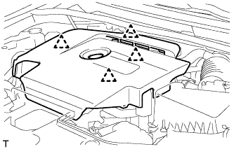
Attach the 4 clips to install the No. 1 engine cover.
-
-
INSTALL ENGINE UNDER COVER
-
Install the engine under cover with the 11 clips.
-
-
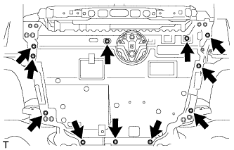
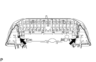
INSTALL FRONT LOWER BUMPER ABSORBER
-
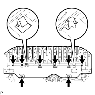
Insert the 2 hooks of the front lower bumper absorber into the installation holes on the body to install the front lower bumper absorber.
-
Install the 8 bolts.
-
Install the 2 clips.
-
-
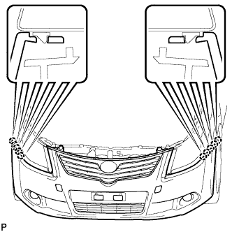
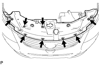
INSTALL FRONT BUMPER COVER
-
Attach the 10 claws to install the front bumper cover.
-
w/ Fog Light:
Connect the 2 fog light connectors and attach the 10 claws to install the front bumper cover.
-
w/ Headlight Cleaner System:
Connect the headlight cleaner hose and attach the 10 claws to install the front bumper cover.
-
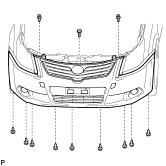
Install the bolt, 2 clips and 9 screws.
-
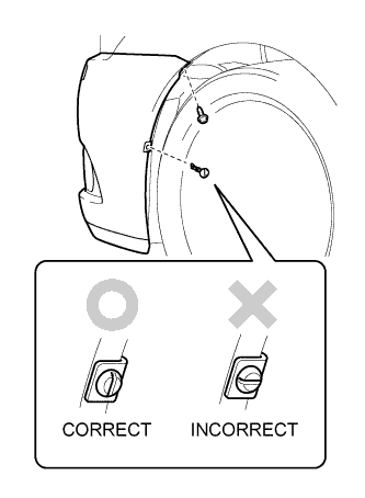
Install the pin hold clip.
Note
Insert the pin hold clip with the slot aligned vertically. Do not rotate the clip after inserting it. After installation, confirm that the slot is vertical.
Tech Tips
Use the same procedures for the RH side and LH side.
-
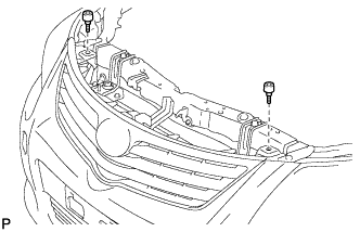
Install the screw.
Tech Tips
Use the same procedures for the RH side and LH side.
-
-
INSTALL RADIATOR GRILLE PROTECTOR
-
Install the 2 radiator grille protectors.
-
-
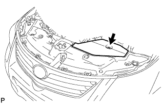
INSTALL RADIATOR SUPPORT OPENING COVER
-
Install the radiator support opening cover with the 8 clips.
-
-
INSTALL ENGINE ROOM SIDE COVER
-
Install the engine room side cover with the clip.
-