EXHAUST FUEL ADDITION INJECTOR INSTALLATION

-
INSTALL FUEL INJECTOR SEAL
-
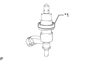
Text in Illustration *1 Fuel Injector Seal Install a new fuel injector seal to the exhaust fuel addition injector.
-
-
INSTALL EXHAUST FUEL ADDITION INJECTOR ASSEMBLY
Note
If there is foreign matter on the installation surface of the exhaust fuel addition injector, be sure to clean it before installation.
-
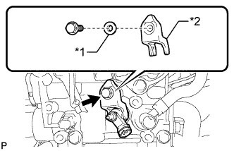
Install a new gasket, the exhaust fuel addition injector, nozzle holder clamp and washer with the bolt.
- Torque:
- 29 N*m { 296 kgf*cm, 21 ft.*lbf }
Text in Illustration *1 Washer *2 Nozzle Holder Clamp Tech Tips
Align the nozzle holder clamp with the cutouts of the injector as shown in the illustration.
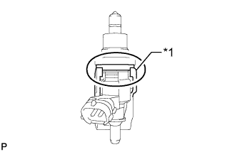
Text in Illustration *1 Nozzle Holder Clamp
-
-
INSTALL FUEL TUBE SUB-ASSEMBLY
-

Text in Illustration *1 Check Valve Temporarily install the fuel tube and 2 new gaskets with the check valve and union bolt.
-
Tighten the check valve.
- Torque:
- 32 N*m { 321 kgf*cm, 23 ft.*lbf }
-
Tighten the union bolt.
- Torque:
- 23 N*m { 235 kgf*cm, 17 ft.*lbf }
-
Connect the fuel tube connector to the injector.
-
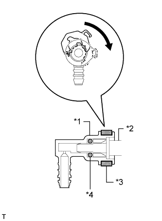
Text in Illustration *1 Fuel Tube Connector *2 Injector *3 Retainer *4 O-Ring Turn the retainer in the direction indicated by the arrow until it makes a "click" sound.
Note
If the fuel tube connector is not inserted to the correct position on the injector, the retainer cannot be turned far enough in the direction of the arrow.
-
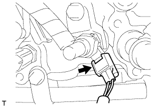
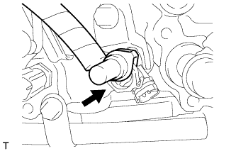
Connect the exhaust fuel addition injector connector.
-
-
INSTALL FUEL HOSE PROTECTOR
-
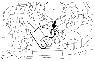
Install the fuel hose protector with the bolt.
- Torque:
- 21 N*m { 209 kgf*cm, 15 ft.*lbf }
-
-
INSTALL WIRE HARNESS CLAMP BRACKET
-
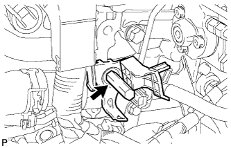
Install the wire harness clamp bracket with the bolt.
- Torque:
- 21 N*m { 214 kgf*cm, 15 ft.*lbf }
-
-
CONNECT WIRE HARNESS
-
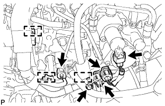
Install the bolt to the fuel hose protector.
- Torque:
- 13 N*m { 133 kgf*cm, 10 ft.*lbf }
-
Connect the 4 connectors and attach the 3 wire harness clamps.
-
-
INSTALL AIR CLEANER CASE SUB-ASSEMBLY
-
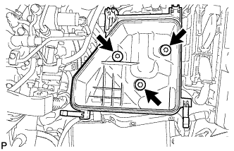
Install the air cleaner case with the 3 bolts.
- Torque:
- 7.0 N*m { 71 kgf*cm, 62 in.*lbf }
-
-
INSTALL AIR CLEANER FILTER ELEMENT SUB-ASSEMBLY
-
INSTALL AIR CLEANER CAP SUB-ASSEMBLY
-
Connect the air cleaner hose.
-
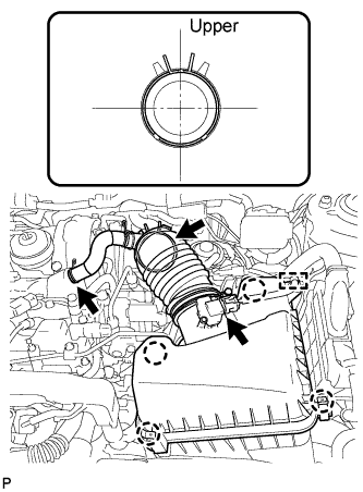
Attach the 4 clamps to install the air cleaner cap.
-
Connect the No. 2 ventilation hose.
-
Attach the clamp and connect the mass air flow meter connector.
-
-
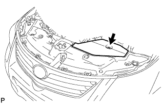
INSTALL COWL TOP VENTILATOR LOUVER
-
Install the cowl top ventilator louver Click here.
-
-
CONNECT CABLE TO NEGATIVE BATTERY TERMINAL
Note
When disconnecting the cable, some systems need to be initialized after the cable is reconnected Click here.
-
INSTALL ENGINE ROOM SIDE COVER
-
Install the engine room side cover with the clip.
-
-
INSPECT FOR FUEL LEAK
Tech Tips
Using the intelligent tester to perform Active Tests allow relays, VSVs, actuators and other items to be operated without removing any parts. This non-intrusive functional inspection can be very useful because intermittent operation may be discovered before parts or wiring is disturbed. Performing Active Tests early in troubleshooting is one way to save diagnostic time. Data List information can be displayed while performing Active Tests.
-
Perform Active Test.
-
Connect the intelligent tester to the DLC3.
-
Turn the ignition switch to ON.
-
Start the engine.
-
Turn the intelligent tester on.
-
Enter the following menus: Powertrain / Engine / Active Test.
-
Perform the Active Test.
Tester Display Test Part Control Range Diagnostic Notes Test the Fuel Leak Pressurizes common rail internal fuel pressure, and checks for fuel leaks Stop/Start Performs inspection of the high pressure fuel system.
-
Engine Speed: 2050 rpm
-
Fuel Pressure: 172000 kPa
-
Target Common Rail Pressure: 176000 kPa
-
Target Pump SCV Current: 1.4 A
-
MAP: 176 kPa
-
MAF: 39 g/sec.
-
-
-
-
INSTALL NO. 1 ENGINE COVER
-
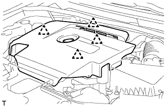
Attach the 4 clips to install the No. 1 engine cover.
-