ENGINE ASSEMBLY INSTALLATION

-
REMOVE ENGINE FROM ENGINE STAND
-
Install a sling device and chain block to the engine and hang the engine.
-
Remove the engine from the engine stand.
-
-
INSTALL FLYWHEEL SUB-ASSEMBLY
-
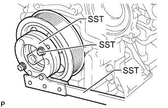
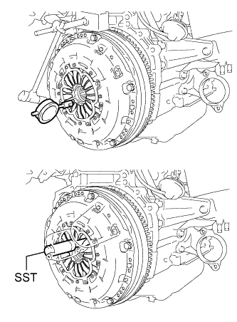
Hold the crankshaft pulley with SST.
- SST
- 09213-58014 ( 91551-80840 )
- 09330-00021
-
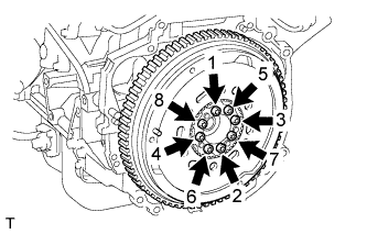
Using a T55 "TORX" socket wrench, install 8 new bolts and uniformly tighten the bolts in several steps in the sequence shown in the illustration.
- Torque:
- 71 N*m { 720 kgf*cm, 52 ft.*lbf }
Note
-
Do not reuse the flywheel installation bolts.
-
Be sure to check the tightening torque within 5 minutes after tightening.
-
Do not impact or damage the flywheel installation bolts. Be sure to handle them carefully.
-
Make sure there is no oil on the bolts.
Tech Tips
Make sure that the seating surface of the flywheel installation bolts and installation surfaces of the crankshaft and flywheel are free from oil and foreign matter.
-
-
INSTALL CLUTCH DISC ASSEMBLY
-
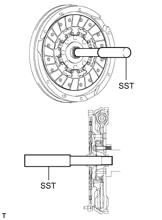
Insert SST into the clutch disc, and then insert them into the flywheel.
- SST
- 09301-00310
Note
Insert the clutch disc with the disc facing the correct direction.
-
-
INSTALL CLUTCH COVER ASSEMBLY
-
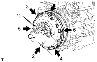
Text in Illustration *1 Matchmark Align the matchmark on the clutch cover with the one on the flywheel.
-
Install and tighten the 6 bolts uniformly in the order shown in the illustration, starting with the bolt located near the knock pin on the top.
- Torque:
- 19 N*m { 195 kgf*cm, 14 ft.*lbf }
Note
-
Be sure to uniformly tighten the bolts 180° at a time according to the order in the illustration.
-
Move SST up and down, right and left lightly after checking that the clutch disc assembly is in the center, and then tighten the bolts.
-
-
INSPECT AND ADJUST CLUTCH COVER ASSEMBLY
-
Using a dial indicator with a roller instrument, measure the diaphragm spring tip alignment.
Maximum misalignment 1.3 mm (0.0512 in.) If the alignment is not as specified, using SST, adjust the diaphragm spring tip alignment.
- SST
- 09333-00013
-
-
INSTALL MANUAL TRANSAXLE ASSEMBLY
-
Install the manual transaxle assembly Click here.
-
-
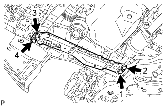
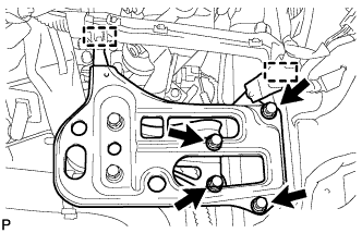
INSTALL STIFFENER PLATE LH
-
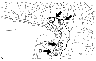
Temporarily install the stiffener plate with the 4 bolts.
-
While holding the stiffener plate against the transaxle, tighten bolt A, and then tighten bolts B, C and D.
- Torque:
- 46 N*m { 469 kgf*cm, 34 ft.*lbf }
-
-
INSTALL STIFFENER PLATE RH
-
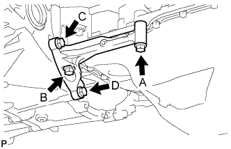
Temporarily install the stiffener plate with the 4 bolts.
-
While holding the stiffener plate against the transaxle, tighten bolt A, and then tighten bolts B, C and D.
- Torque:
- 46 N*m { 469 kgf*cm, 34 ft.*lbf }
-
-
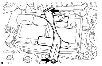
INSTALL OIL PAN INSULATOR
-
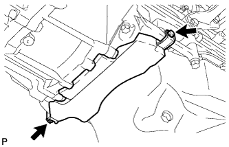
Install the oil pan insulator with the 2 bolts.
- Torque:
- 9.0 N*m { 92 kgf*cm, 80 in.*lbf }
-
-
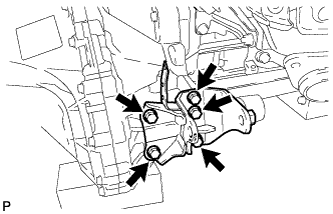
INSTALL ENGINE MOUNTING INSULATOR RH
Tech Tips
Perform this procedure only when replacement of the engine mounting insulator is necessary.
-
Install the engine mounting insulator with the 3 bolts.
- Torque:
- 95 N*m { 969 kgf*cm, 70 ft.*lbf }
-
-
INSTALL ENGINE MOUNTING INSULATOR LH
Tech Tips
Perform this procedure only when replacement of the engine mounting insulator is necessary.
-
Install the engine mounting insulator with the 4 bolts.
- Torque:
- 95 N*m { 969 kgf*cm, 70 ft.*lbf }
-
-
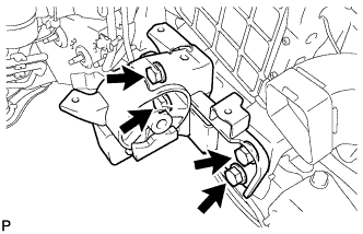
INSTALL ENGINE MOUNTING BRACKET LH
Tech Tips
Perform this procedure only when replacement of the engine mounting bracket is necessary.
-
Install the engine mounting bracket LH with the 4 bolts.
- Torque:
- 64 N*m { 653 kgf*cm, 47 ft.*lbf }
-
-
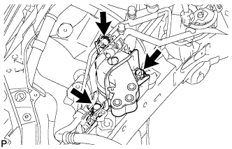
INSTALL REAR ENGINE MOUNTING BRACKET
-
Install the rear engine mounting bracket with the 5 bolts.
- Torque:
- 45 N*m { 459 kgf*cm, 33 ft.*lbf }
-
-
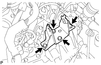
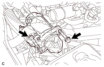
INSTALL FRONT ENGINE MOUNTING BRACKET
-
Install the front engine mounting bracket with the 3 bolts.
- Torque:
- 64 N*m { 653 kgf*cm, 47 ft.*lbf }
-
-
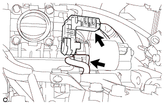
INSTALL ENGINE WIRE
-
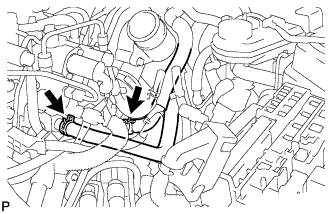
Connect the connectors and clamps, and install the engine wire to the engine with the bracket bolts.
-
-
INSTALL STARTER ASSEMBLY (for VALEO Made)
-
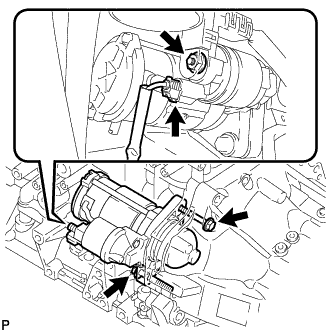
Install the starter with the 2 bolts.
- Torque:
- 64 N*m { 653 kgf*cm, 47 ft.*lbf }
-
Connect the starter wire with the nut and close the terminal cap.
- Torque:
- 9.8 N*m { 100 kgf*cm, 87 in.*lbf }
-
Connect the starter connector.
-
-
INSTALL STARTER ASSEMBLY (for DENSO Made)
-
Install the starter with the 2 bolts.
- Torque:
- 64 N*m { 652 kgf*cm, 47 ft.*lbf }
-
Connect the starter wire with the nut and close the terminal cap.
- Torque:
- 9.8 N*m { 100 kgf*cm, 87 in.*lbf }
-
Connect the starter connector.
-
-
INSTALL NO. 1 AIR TUBE
-
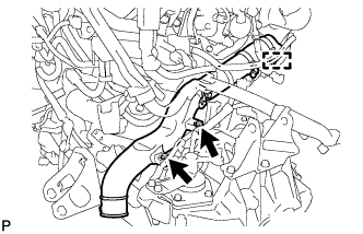
Install the No. 1 air tube with the 2 bolts and tighten the clamp.
- Torque:
- for bolt
- 20 N*m { 204 kgf*cm, 15 ft.*lbf }
- for clamp
- 6.5 N*m { 66 kgf*cm, 58 in.*lbf }
Note
Before installation, remove any oil residue from the inside of the tube and hose.
-
-
INSTALL REAR ENGINE MOUNTING INSULATOR
-
Install the rear engine mounting insulator with the 3 bolts and 2 nuts.
- Torque:
- 95 N*m { 969 kgf*cm, 70 ft.*lbf }
-
-
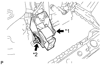
INSTALL ENGINE WITH TRANSAXLE
-
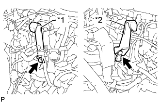
Text in Illustration *1 No. 1 Engine Hanger *2 No. 2 Engine Hanger Install the No. 1 and No. 2 engine hangers with 2 bolts as shown in the illustration.
- Torque:
- 40 N*m { 408 kgf*cm, 30 ft.*lbf }
Tech Tips
Part No. No. 1 engine hanger 12281-26040 No. 2 engine hanger 12282-26010 Bolt 91552-81025 or 90105-W0042
-
Insert the claw of the No. 1 engine hanger into the hole of the cylinder head.
-
Fit the fork part of the No. 2 engine hanger onto the rib of the cylinder head.
-
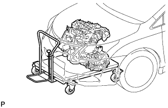
Place the engine on an engine lifter.
Tech Tips
Place the engine on wooden blocks or equivalent so that the engine is level.
-
Using the chain block, slowly install the engine to the vehicle and the intermediate shaft to the pinion.
CAUTION:
Do not raise the engine more than necessary. If the engine is raised excessively, the vehicle may also be lifted up.
Note
-
Make sure that the engine is clear of all wiring and hoses.
-
While raising the engine into the vehicle, do not allow it to contact the vehicle.
-
Align the matchmarks on the intermediate shaft and pinion.
-
-
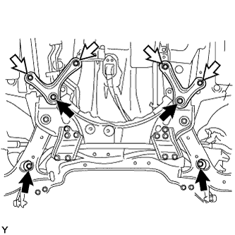
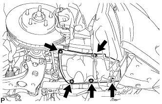
Temporarily install the suspension crossmember with 2 new bolts.
Text in Illustration 
New Bolt 
Bolt -
Temporarily install the rear brace RH and LH with 2 new bolts and the 4 bolts.
-
Connect the engine mounting insulator LH with the bolt and nut.
- Torque:
- 56 N*m { 571 kgf*cm, 41 ft.*lbf }
Tech Tips
While holding the bolt in place, tighten the nut.
-
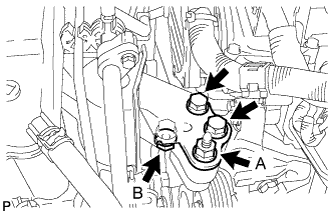
Connect the engine mounting insulator RH with the 2 bolts and 2 nuts.
- Torque:
- for bolt, nut A
- 95 N*m { 969 kgf*cm, 70 ft.*lbf }
- for nut B
- 52 N*m { 530 kgf*cm, 38 ft.*lbf }
-
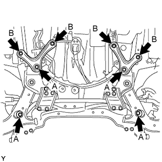
Tighten the 8 suspension crossmember and rear brace bolts.
- Torque:
- for bolt A
- 137 N*m { 1397 kgf*cm, 101 ft.*lbf }
- for bolt B
- 93 N*m { 948 kgf*cm, 69 ft.*lbf }
-
Remove the 2 bolts, No. 1 and No. 2 engine hangers.
-
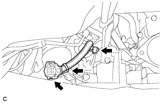
Attach the 3 clamps and connect the wire harness.
-
Connect the cable bracket with the bolt.
- Torque:
- 5.0 N*m { 51 kgf*cm, 44 in.*lbf }
-
-
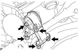
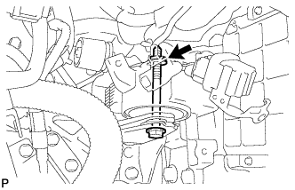
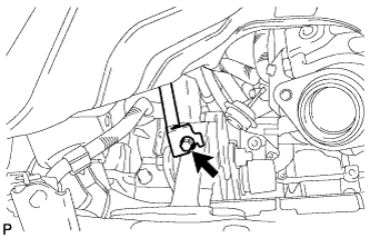
INSTALL FRONT ENGINE MOUNTING INSULATOR
-
Text in Illustration *1 Through Bolt *2 Nut Install the front engine mounting insulator with through bolt and nut.
- Torque:
- 145 N*m { 1479 kgf*cm, 107 ft.*lbf }
-
-
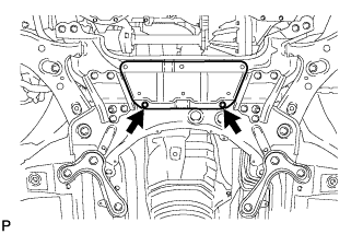
INSTALL FRONT CROSSMEMBER SUB-ASSEMBLY
-
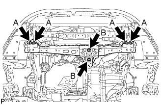
Install the front crossmember with the 6 bolts.
- Torque:
- for bolt A
- 96 N*m { 979 kgf*cm, 71 ft.*lbf }
- for bolt B
- 95 N*m { 969 kgf*cm, 70 ft.*lbf }
-
-
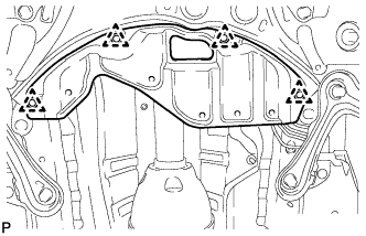
INSTALL FRONT SUSPENSION MEMBER REINFORCEMENT LH
-
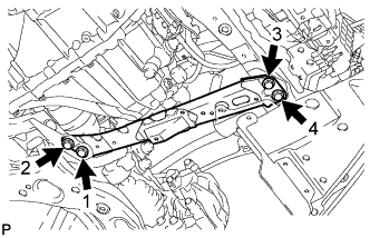
Install the front suspension member reinforcement with the 4 bolts.
- Torque:
- 96 N*m { 979 kgf*cm, 71 ft.*lbf }
Note
Tighten the bolts in the order shown in the illustration.
-
-
INSTALL FRONT DRIVE SHAFT ASSEMBLY LH
-
Coat the spline of the inboard joint shaft with oil.
Tech Tips
Be sure to use the same type of oil that is used for the transaxle.
-
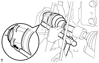
Align the shaft splines and tap in the drive shaft with a brass bar and hammer.
Note
-
Make sure that the snap ring opening is facing downwards when installing the drive shaft.
-
Be careful not to damage the oil seal, boot or dust cover.
-
-
-
INSTALL FRONT DRIVE SHAFT ASSEMBLY RH
-
Coat the spline of the inboard joint shaft with gear oil.
-
Align the shaft splines and securely insert the drive shaft.
-
Install the 2 bearing bracket bolts.
- Torque:
- 64 N*m { 650 kgf*cm, 47 ft.*lbf }
Note
Do not damage the oil seal, boot or dust cover.
-
-
INSTALL FRONT AXLE ASSEMBLY LH
-
Install the front axle assembly LH Click here.
-
-
INSTALL FRONT AXLE ASSEMBLY RH
Tech Tips
Use the same procedures described for the LH side.
-
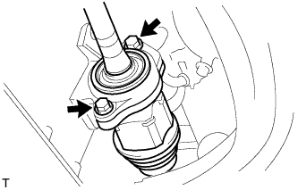
CONNECT FRONT STABILIZER LINK ASSEMBLY LH
-
Remove the nut and disconnect the stabilizer link assembly from the front shock absorber with coil spring.
Tech Tips
If the ball joint turns together with the nut, use a 6 mm hexagon wrench to hold the stud bolt.
-
-
CONNECT FRONT STABILIZER LINK ASSEMBLY RH
Tech Tips
Perform the same procedure as for the LH side.
-
INSTALL FRONT AXLE SHAFT NUT LH
-
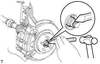
Using a chisel and a hammer, stake the front axle shaft nut.
-
-
INSTALL FRONT AXLE SHAFT NUT RH
Tech Tips
Perform the same procedure as for the LH side.
-
INSTALL NO. 1 STEERING COLUMN HOLE COVER SUB-ASSEMBLY
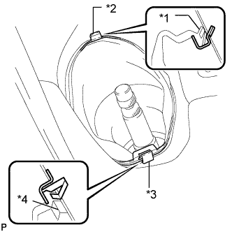
Text in Illustration *1 Lip *2 Clip B *3 Clip A *4 Lip
-
Attach clip B to the body and install the No. 1 steering column hole cover to the body with clip A.
Note
Make sure that the lip of the No. 1 steering column hole cover is not damaged.
-
-
CONNECT NO. 2 STEERING INTERMEDIATE SHAFT ASSEMBLY
-
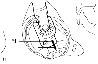
Text in Illustration *1 Matchmark Align the matchmarks on the No. 2 steering intermediate shaft assembly and steering intermediate shaft assembly.
-
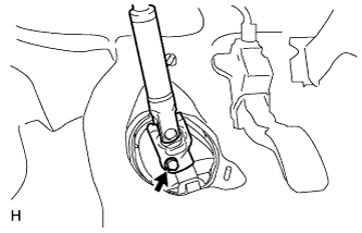
Install the bolt.
- Torque:
- 35 N*m { 360 kgf*cm, 26 ft.*lbf }
-
-
INSTALL COLUMN HOLE COVER SILENCER SHEET
-
Install the column hole cover silencer sheet with the 2 clips.
-
Install the floor carpet.
-
-
CONNECT CLUTCH RELEASE CYLINDER ASSEMBLY
-
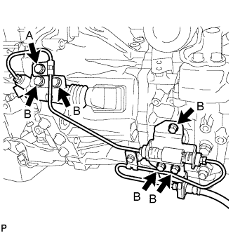
Connect the release cylinder and flexible hose bracket with the 6 bolts.
- Torque:
- for bolt A
- 8.0 N*m { 82 kgf*cm, 71 in.*lbf }
- for bolt B
- 12 N*m { 122 kgf*cm, 9 ft.*lbf }
-
-
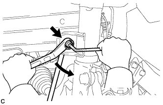
CONNECT TRANSMISSION CONTROL CABLE ASSEMBLY
-
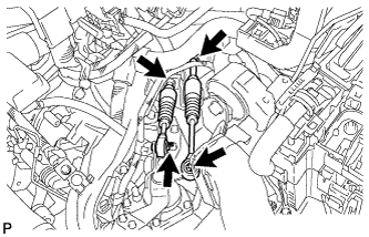
Connect the control cable to the control cable bracket with 2 new clips.
-
Connect the control cable to the transaxle with the 2 pins.
-
-
CONNECT COMPRESSOR WITH PULLEY ASSEMBLY (w/ Air Conditioning System)
-
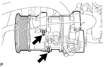
Using an E8 "TORX" socket wrench, connect the compressor with the 2 stud bolts.
- Torque:
- 9.8 N*m { 100 kgf*cm, 87 in.*lbf }
-
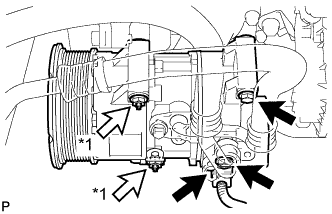
Text in Illustration *1 Nut Install the 2 bolts and 2 nuts.
- Torque:
- 25 N*m { 255 kgf*cm, 18 ft.*lbf }
-
Connect the connector.
-
-
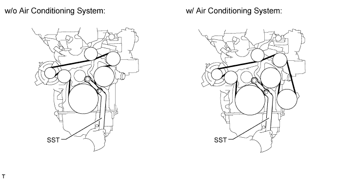
INSTALL FAN AND GENERATOR V BELT
-
Using SST and a 22 mm wrench, rotate the tensioner pulley counterclockwise, and then install the fan and generator V belt.
- SST
- 09216-42010
CAUTION:
-
Be careful as the wrench only fits loosely on the belt tensioner tool set point. The wrench may come off the set point and cause injuries.
-
Be careful that your hands do not become jammed between parts such as the belt, pulleys, etc.
Note
-
Make sure that the belt is set properly on each pulley.
-
Make sure SST is installed as shown in the illustration. If not, SST and/or the belt may not be able to be removed.
-
-
INSTALL FRONT SUSPENSION MEMBER REINFORCEMENT RH
-
Install the front suspension member reinforcement with the 4 bolts.
- Torque:
- 96 N*m { 979 kgf*cm, 71 ft.*lbf }
Note
Tighten the bolts in the order shown in the illustration.
-
-
INSTALL INJECTOR DRIVER
-
Install the injector driver with the 3 screws.
- Torque:
- 6.0 N*m { 61 kgf*cm, 53 in.*lbf }
-
Attach the clamp and connect the 4 connectors.
-
-
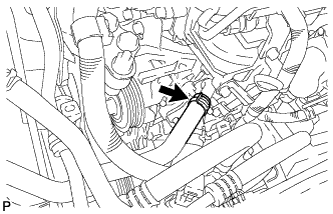
CONNECT NO. 2 RADIATOR HOSE
-
Connect the No. 2 radiator hose.
-
-
CONNECT WATER BY-PASS HOSE
-
Connect the water by-pass hose.
-
-
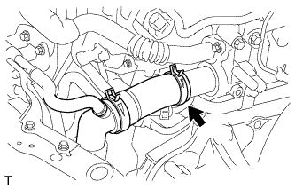
INSTALL INTERCOOLER AIR HOSE
Note
-
Check that the retainer is closed when the connector is inserted.
-
If replacing the hose, check for deposits in the intercooler and intercooler air hose. If necessary, wipe up deposits.
-
If replacing the hose, apply fresh oil to the O-ring.
-
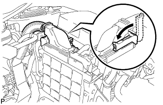
Push on the connector until it makes a click sound which indicates that the connection is complete. After connecting the connector, check that the connector cannot be disconnected by pulling the connector.
-
Do not use a quick connector that has been dropped.
-
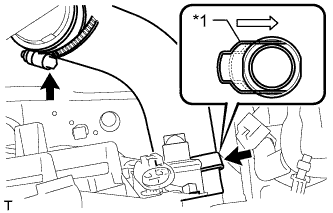
Install the intercooler air hose to the intercooler and No. 1 air tube and push in the retainer.
-
Tighten the hose clamp.
- Torque:
- 6.5 N*m { 66 kgf*cm, 58 in.*lbf }
-
-
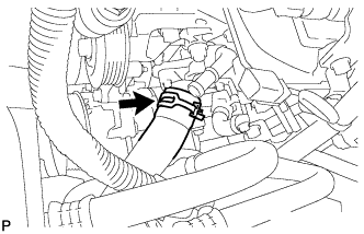
CONNECT NO. 1 RADIATOR HOSE
-
Connect the No. 1 radiator hose.
-
-
CONNECT INLET HEATER WATER HOSE
-
Connect the inlet heater water hose.
-
-
CONNECT OUTLET HEATER WATER HOSE
-
Connect the outlet heater water hose
-
-
CONNECT HOSES AND CONNECTORS
-
Connect the vacuum pump hose.
-
Connect the 2 fuel hoses.
-
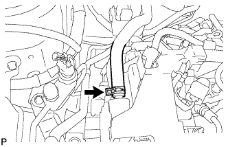
Connect the ECM connector and lower the lever.
Note
-
When connecting the connector, make sure that dirt, water and other foreign matter is not stuck between the connector and ECM.
-
Make sure that the lever is securely lowered.
-
-
Attach the 4 clamps and connect the wire harness.
-
Install the air cleaner bracket with the 5 bolts.
- Torque:
- 7.0 N*m { 71 kgf*cm, 62 in.*lbf }
-
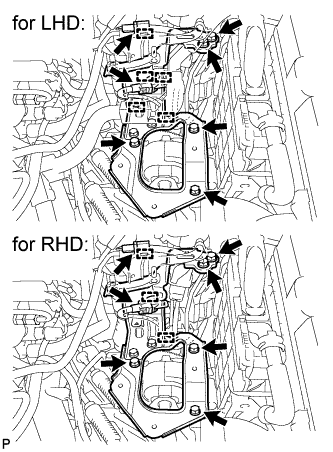
for LHD:
Attach the 5 clamps and connect the 2 connectors.
-
for RHD:
Attach the 3 clamps and connect the 2 connectors.
-
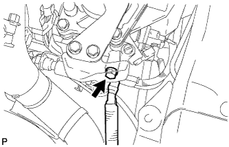
Connect the ground cable with the bolt.
- Torque:
- 13 N*m { 127 kgf*cm, 9 ft.*lbf }
-
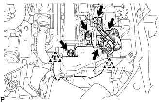
Connect the 3 connectors, attach the 2 claws to install the No. 1 engine room relay block and install the 2 nuts.
- Torque:
- 8.4 N*m { 86 kgf*cm, 74 in.*lbf }
-
Connect the current sensor connector.
-
Install the engine room No. 1 relay block cover.
-
-
INSTALL FUEL FILTER ASSEMBLY (w/o Combustion Type Power Heater)
-
Install the fuel filter assembly with the 2 nuts.
- Torque:
- 18 N*m { 178 kgf*cm, 13 ft.*lbf }
-
Connect the level warning switch connector.
-

Connect the No. 1 fuel hose, No. 2 fuel hose and No. 3 fuel hose.
Tech Tips
-
Align the alignment marks and connect the hose.
-
Align the claws of the clamp with the hose alignment mark as shown in the illustration.
-
Position the clamp so that the distance from the end of the hose is 1 to 5 mm (0.0394 to 0.197 in.).
-
-
Connect the No. 4 fuel hose.
Tech Tips
Make sure the direction of the hose clamp is as shown in the illustration.
-
-
INSTALL FUEL FILTER ASSEMBLY (w/ Combustion Type Power Heater)
-
Install the fuel filter assembly with the 2 nuts.
- Torque:
- 18 N*m { 178 kgf*cm, 13 ft.*lbf }
-
Connect the level warning switch connector.
-

Connect the No. 1 fuel hose, No. 2 fuel hose and No. 3 fuel hose.
Tech Tips
-
Align the alignment marks and connect the hose.
-
Align the claws of the clamp with the hose alignment mark as shown in the illustration.
-
Position the clamp so that the distance from the end of the hose is 1 to 5 mm (0.0394 to 0.197 in.).
-
-
Connect the No. 4 fuel hose.
Tech Tips
Make sure the direction of the hose clamp is as shown in the illustration.
-
Connect the heater fuel hose.
Tech Tips
-
Align the alignment marks and connect the hose.
-
Make sure the direction of the hose clamp is as shown in the illustration.
-
-
-
INSTALL AIR CLEANER CASE
-
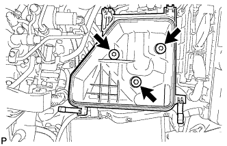
Install the air cleaner case with the 3 bolts.
- Torque:
- 7.0 N*m { 71 kgf*cm, 62 in.*lbf }
-
-
INSTALL AIR CLEANER FILTER ELEMENT SUB-ASSEMBLY
-
INSTALL AIR CLEANER CAP SUB-ASSEMBLY
-
Connect the air cleaner hose.
-
Attach the 4 clamps to install the air cleaner cap.
-
Connect the No. 2 ventilation hose.
-
Connect the mass air flow meter connector.
-
-
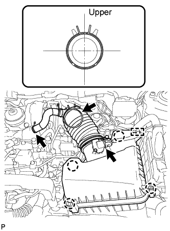
INSTALL NO. 3 AIR HOSE
Note
Before installation, remove any oil residue from the inside of pipe and hose.
-
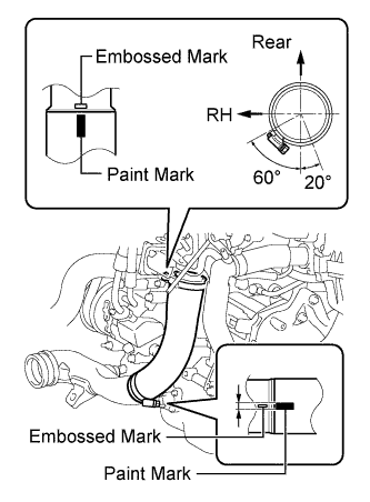
Align the paint mark of the No. 3 air hose with the embossed mark of the throttle body.
-
Align the paint mark of the No. 3 air hose with the embossed mark of the No. 2 air tube.
-
Tighten the clamp of the No. 3 air hose on the diesel throttle body side.
- Torque:
- 6.5 N*m { 66 kgf*cm, 58 in.*lbf }
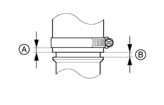
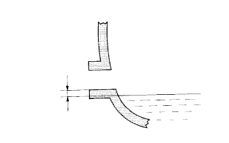
Tech Tips
-
Align the paint mark of the air hose with the embossed mark and push in the air hose so that distance B is 0 to 2 mm (0 to 0.0787 in.).
-
Position the clamp so that distance A is 4 to 9 mm (0.157 to 0.354 in.).
-
Tighten the clamp of the No. 3 air hose on the No. 2 air tube side.
- Torque:
- 6.5 N*m { 66 kgf*cm, 58 in.*lbf }
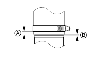
Tech Tips
-
Align the paint mark of the air hose with the embossed mark and push in the air hose so that distance B is 0 to 2 mm (0 to 0.0787 in.).
-
Position the clamp so that distance A is 9 to 15 mm (0.354 to 0.591 in.).
-
-
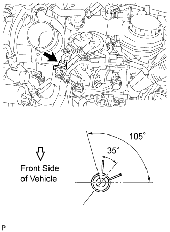
CONNECT NO. 2 VACUUM TRANSMITTING HOSE ASSEMBLY
-
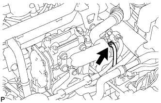
Connect the No. 2 vacuum transmitting hose to the intake manifold.
-
-
INSTALL BATTERY CARRIER
-
Install the battery carrier with the 4 bolts.
- Torque:
- 19 N*m { 189 kgf*cm, 14 ft.*lbf }
-
Attach the 2 clamps to connect the wire harness.
-
-
INSTALL BATTERY TRAY
-
INSTALL BATTERY
-
INSTALL BATTERY CLAMP SUB-ASSEMBLY
-
Attach the hook of the battery clamp to the battery carrier.
-
Partially tighten the nut and temporarily install the bolt.
-
Adjust the battery clamp position.
-
Tighten the nut and bolt.
- Torque:
- for bolt
- 17 N*m { 168 kgf*cm, 12 ft.*lbf }
- for nut
- 3.5 N*m { 36 kgf*cm, 31 in.*lbf }
-
-
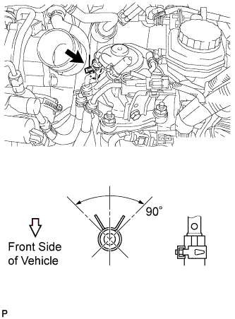
INSTALL DIFFERENTIAL PRESSURE SENSOR ASSEMBLY
-
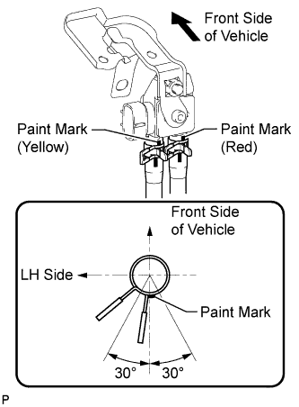
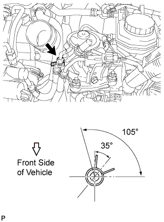
Connect the 2 vacuum hoses.
Note
Connect the vacuum hoses so that the painted marks of the 2 vacuum hoses are as shown in the illustration.
-
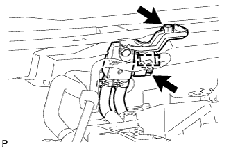
Install the sensor with the bolt.
- Torque:
- 8.0 N*m { 82 kgf*cm, 71 in.*lbf }
-
Connect the sensor connector and attach the wire harness clamp.
-
-
INSTALL FRONT EXHAUST PIPE ASSEMBLY
-
Install the front exhaust pipe Click here.
-
-
ADD MANUAL TRANSAXLE OIL
-
Add oil until the oil level is within 5 mm (0.197 in.) from the bottom of the transmission filler plug opening.
-
Install a new gasket and the transmission filler plug.
- Torque:
- 39 N*m { 400 kgf*cm, 29 ft.*lbf }
Note
-
When adding transaxle oil, make sure the vehicle is level.
-
An excessively large or small amount of oil may cause problems.
-
After adding oil, drive the vehicle and recheck the oil level.
-
-
INSPECT FOR MANUAL TRANSAXLE OIL LEAK
-
ADD ENGINE OIL
-
Add new engine oil.
Standard Oil Grade Oil Grade Oil Viscosity (SAE) ACEA C2 - 0W-30
- 5W-30
Standard Capacity Item Specified Condition Drain and refill with oil filter change 5.9 liters (6.2 US qts, 5.2 Imp. qts) Drain and refill without oil filter change 5.5 liters (5.8 US qts, 4.8 Imp. qts) Dry fill 6.7 liters (7.1 US qts, 5.9 Imp. qts)
-
-
ADD ENGINE COOLANT
-
Tighten the radiator drain cock plug by hand.
-
Tighten the cylinder block drain cock plug.
- Torque:
- for Type A
- 13 N*m { 130 kgf*cm, 9 ft.*lbf }
- for Type B
- 25 N*m { 255 kgf*cm, 18 ft.*lbf }
-
Add TOYOTA Super Long Life Coolant (SLLC) to the radiator reservoir filler opening.
Standard Capacity Item Specified Condition w/o Power Heater 7.4 liters (7.8 US qts, 6.5 Imp. qts) w/ Power Heater 7.8 liters (8.2 US qts, 6.9 Imp. qts) Tech Tips
TOYOTA vehicles are filled with TOYOTA SLLC at the factory. In order to avoid damage to the engine cooling system and other technical problems, only use TOYOTA SLLC or similar high quality ethylene glycol based non-silicate, non-amine, non-nitrite, non-borate coolant with long-life hybrid organic acid technology (coolant with long-life hybrid organic acid technology is a combination of low phosphates and organic acids).
Note
Never use water as a substitute for engine coolant.
-
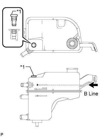
Text in Illustration *1 Air Release Plug Remove the radiator cap and air release plug and add coolant to the B line of the reservoir tank.
-
Squeeze the inlet and outlet radiator hoses several times by hand, and then check the level of the coolant.
If the coolant level is low, add coolant.
-
Install the cap and air release plug, and warm up the engine sufficiently.
- Torque:
- 2.0 N*m { 20 kgf*cm, 18 in.*lbf }
-
Bleed air from the cooling system.
Note
-
Before starting the engine, turn the A/C switch off.
-
Adjust the air conditioning temperature setting to MAX (HOT).
-
Adjust the air conditioning blower setting to Lo.
-
Warm up the engine until the thermostat opens. While the thermostat is open, allow the coolant to circulate for several minutes.
Tech Tips
The thermostat opening timing can be confirmed by squeezing the inlet radiator hose by hand and sensing vibrations when the engine coolant starts to flow inside the hose.
CAUTION:
When squeezing the radiator hoses:
-
Wear protective gloves.
-
Be careful as the radiator hoses are hot.
-
Keep your hands away from the radiator fan.
-
-
After the engine has warmed up, run the engine according to the following pattern for at least 7 minutes: 3000 rpm for 5 seconds, and then idle speed for 45 seconds (repeat this pattern at least 8 times).
-
Squeeze the inlet and outlet radiator hoses several times by hand to bleed air from the system.
CAUTION:
When squeezing the radiator hoses:
-
Wear protective gloves.
-
Be careful as the radiator hoses are hot.
-
Keep your hands away from the radiator fan.
-
-
-
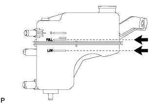
After the engine has cooled down, check that the coolant level is between FULL and LOW.
If the coolant level is low, add coolant until the coolant level reaches the reservoir tank FULL line.
-
-
CONNECT CABLE TO POSITIVE BATTERY TERMINAL
-
CONNECT CABLE TO NEGATIVE BATTERY TERMINAL
Note
When disconnecting the cable, some systems need to be initialized after the cable is reconnected Click here.
-
BLEED FUEL SYSTEM
-
Using the hand pump mounted on the fuel filter cap, bleed the air from the fuel system. Continue pumping until the pump resistance increases.
Note
-
Hand pump pumping speed: Max. 2 strokes/ sec.
-
The hand pump must be pushed with a full stroke during pumping.
-
When the fuel pressure at the supply pump inlet port reaches a saturated pressure, the hand pump resistance increases.
-
If pumping is interrupted during the air bleeding process, fuel in the fuel line may return to the fuel tank. Continue pumping until the hand pump resistance increases.
-
If the hand pump resistance does not increase despite consecutively pumping 200 times or more, there may be a fuel leak between the fuel tank and fuel filter, the hand pump may be malfunctioning, or the vehicle may have run out of fuel.
-
If air bleeding using the hand pump is incomplete, the common rail pressure does not rise to the pressure range necessary for normal use, and the engine cannot be started.
-
-
Start the engine.
Note
-
Even if air bleeding using the hand pump has been completed, the starter may need to be cranked for 10 seconds or more to start the engine.
-
Do not crank the engine continuously for more than 20 seconds. The battery may be discharged.
-
Use a fully-charged battery.
-
When the engine can be started, proceed to the next step.
-
If the engine cannot be started, bleed the air again using the hand pump until the hand pump resistance increases (refer to the procedures above). Then start the engine.
-
-
Turn the ignition switch off.
-
Connect the intelligent tester to the DLC3.
-
Turn the ignition switch to ON and turn the intelligent tester on.
-
Clear the DTCs Click here.
-
Start the engine.*1
-
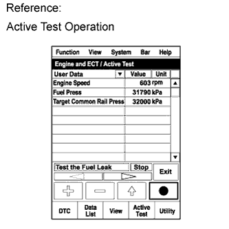
Enter the following menus: Powertrain / Engine and ECT / Active Test / Test the Fuel Leak.*2
-
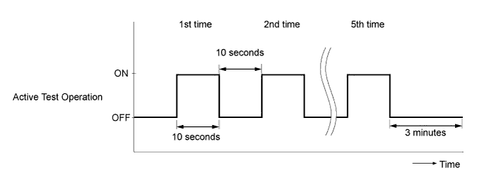
Perform the following test 5 times with on/off intervals of 10 seconds: Active Test / Test the Fuel Leak.*3
-
Allow the engine to idle for 3 minutes or more after performing the Active Test for the fifth time.
Tech Tips
When the Active Test "Test the Fuel Leak" is used to change the pump control mode, the actual fuel pressure inside the common rail drops below the target fuel pressure when the Active Test is off, but this is normal and does not indicate a pump malfunction.
-
Enter the following menus: Powertrain / Engine and ECT / DTC.
-
Read Current DTCs.
-
When no DTCs are output, the air bleeding is completed.
-
If any DTCs are output, proceed to the next step.
-
-
Clear the DTCs Click here.
-
Repeat steps *1 to *3.
-
Enter the following menus: Powertrain / Engine and ECT / DTC.
-
Read Current DTCs.
OK No DTCs are output.
-
-
PERFORM REGISTRATION
-
Perform registration of the injector compensation codes Click here.
-
Perform registration of the pilot quantity learning Click here.
-
-
PERFORM INITIALIZATION
-
Perform initialization of the crank time compensation reset function Click here.
-
-
PERFORM THROTTLE VALVE FULLY CLOSED POSITION LEARNING
Tech Tips
Be sure to turn off the ignition switch before performing this inspection.
-
Turn the ignition switch to ON.
-
Turn the ignition switch off and wait 10 seconds.
Tech Tips
The fully closed position of the diesel throttle valve is learned when the ignition switch is turned off.
-
-
INSPECT FOR OIL LEAK
-
Warm up the engine and check for an engine oil leak.
-
-
INSPECT FOR COOLANT LEAK
-
Remove the radiator reservoir cap.
CAUTION:
To avoid the danger of being burned, do not remove the radiator reservoir cap while the engine and radiator are still hot. Thermal expansion will cause hot engine coolant and steam to blow out from the radiator.
-
Fill the radiator with coolant, and then attach a radiator cap tester.
-
Warm up the engine.
-
Pump the radiator cap tester to 118 kPa (1.2 kgf/cm2, 17 psi), and then check that the pressure does not drop.
If the pressure drops, check the hoses, radiator and water pump for leakage.
If there are no signs of external coolant leaks, check the heater core, cylinder block and head.
-
Reinstall the radiator reservoir cap.
-
-
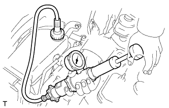
INSPECT FOR FUEL LEAK
Tech Tips
Using the intelligent tester to perform Active Tests allow relays, VSVs, actuators and other items to be operated without removing any parts. This non-intrusive functional inspection can be very useful because intermittent operation may be discovered before parts or wiring is disturbed. Performing Active Tests early in troubleshooting is one way to save diagnostic time. Data List information can be displayed while performing Active Tests.
-
Perform Active Test.
-
Connect the intelligent tester to the DLC3.
-
Turn the ignition switch to ON.
-
Start the engine.
-
Turn the intelligent tester on.
-
Enter the following menus: Powertrain / Engine / Active Test.
-
Perform the Active Test.
Tester Display Test Part Control Range Diagnostic Notes Test the Fuel Leak Pressurizes common rail internal fuel pressure, and checks for fuel leaks Stop/Start Performs inspection of the high pressure fuel system.
-
Engine Speed: 2050 rpm
-
Fuel Pressure: 172000 kPa
-
Target Common Rail Pressure: 176000 kPa
-
Target Pump SCV Current: 1.4 A
-
MAP: 176 kPa
-
MAF: 39 g/sec.
-
-
-
-
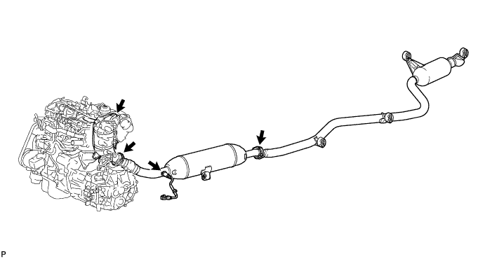
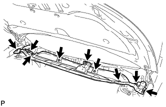
INSPECT FOR EXHAUST GAS LEAK
-
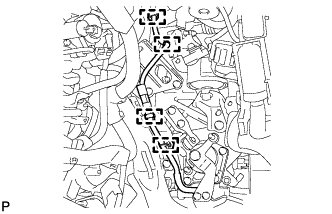
Check that there are no exhaust gas leaks from the points (connection areas of the exhaust pipes and installation areas of each sensor) shown in the illustration.
-
-
INSTALL REAR ENGINE UNDER COVER RH
-
Install the under cover with the 5 clips.
-
-
INSTALL REAR ENGINE UNDER COVER LH
-
Install the under cover with the 5 clips.
-
-
INSTALL NO. 2 ENGINE UNDER COVER
-
Install the No. 2 engine under cover with the 4 clips.
-
-
INSTALL CENTER NO. 4 ENGINE UNDER COVER
-
Install the engine under cover with the 2 clips.
-
-
INSTALL NO. 1 ENGINE UNDER COVER
-
Install the engine under cover with the 11 clips.
-
-
INSTALL FRONT LOWER BUMPER ABSORBER
-
Insert the 2 hooks of the front lower bumper absorber into the installation holes on the body to install the front lower bumper absorber.
-
Install 8 bolts and 3 screws.
-
Install the 4 screws and 2 bolts.
-
-
INSTALL NO. 1 ENGINE COVER
-
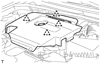
Attach the 4 clips to install the No. 1 engine cover.
-
-
INSTALL OUTER COWL TOP PANEL SUB-ASSEMBLY
-
Install the outer cowl top panel with the 9 bolts.
- Torque:
- 8.8 N*m { 90 kgf*cm, 78 in.*lbf }
-
Attach the clamp and connect the connector.
-
-
INSTALL FRONT WIPER MOTOR AND LINK ASSEMBLY
-
Install the front wiper motor and link Click here.
-
-
INSTALL FRONT WHEEL
-
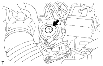
CHECK IDLE SPEED
Note
-
Turn all the electrical systems and A/C off.
-
Inspect the engine idle speed with the cooling fan off.
-
When checking the idle speed, move the shift lever to neutral.
Tech Tips
-
For more information about the intelligent tester, refer to its operator's manual.
-
If an intelligent tester is not available, use a tachometer as a substitute.
-
Warm up and stop the engine.
-
When using the intelligent tester:
-
Connect the intelligent tester to the DLC3.
-
Start the engine and idle it.
-
Enter the following menus: Powertrain / Engine / Data List / Engine SPD.
-
-
When not using the intelligent tester:
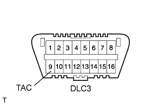
-
Connect a tester probe of a tachometer to terminal 9 (TAC) of the DLC3 with SST.
- SST
- 09843-18030
-
Start the engine and idle it.
-
-
Inspect the engine idle speed.
Standard idle speed 720 to 820 rpm -
Turn the ignition switch off.
-
Disconnect the intelligent tester or tachometer tester probe from the DLC3.
-
-
CHECK MAXIMUM ENGINE SPEED
-
Start the engine.
-
Fully depress the accelerator pedal.
-
Check the maximum engine speed.
Maximum engine speed 5100 to 5250 rpm
-
-
INSTALL RADIATOR SUPPORT OPENING COVER
-
Install the radiator support opening cover with the 8 clips.
-
-
ADJUST FRONT WHEEL ALIGNMENT
-
Adjust the front wheel alignment Click here.
-
-
CHECK ABS SPEED SENSOR SIGNAL
-
Check the speed sensor signal Click here.
-
-
PERFORM CLUTCH ENGAGEMENT POINT LEARNING