ENGINE ASSEMBLY REMOVAL

-
INSPECT DRIVE AWAY RELEASE FUNCTION (for Manual Transaxle)
-
PLACE FRONT WHEELS FACING STRAIGHT AHEAD
-
REMOVE RADIATOR SUPPORT OPENING COVER
-
Remove the 8 clips and radiator support opening cover.
-
-
DISCONNECT CABLE FROM NEGATIVE BATTERY TERMINAL
Note
-
When disconnecting the cable, some systems need to be initialized after the cable is reconnected Click here.
-
w/ Navigation System (for HDD):
After the ignition switch is turned off, the HDD navigation system requires approximately a minute to record various types of memory and settings. As a result, after turning the ignition switch off, wait a minute or more before disconnecting the cable from the negative (-) battery terminal.
-
-
DISCONNECT CABLE FROM POSITIVE BATTERY TERMINAL
-
REMOVE FRONT WHEEL
-
REMOVE FRONT WIPER MOTOR AND LINK ASSEMBLY
-
Remove the front wiper motor and link Click here.
-
-
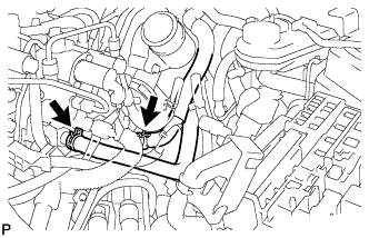
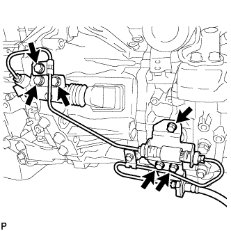
REMOVE DIFFERENTIAL PRESSURE SENSOR ASSEMBLY
-
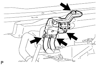
Detach the wire harness clamp and disconnect the sensor connector.
-
Remove the bolt and sensor.
-
Disconnect the 2 vacuum hoses.
-
-
REMOVE OUTER COWL TOP PANEL SUB-ASSEMBLY
-
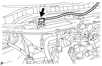
Disconnect the connector and detach the harness clamp.
-
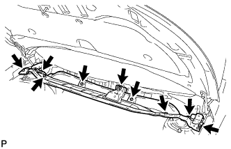
Remove the 9 bolts and outer cowl top panel.
-
-
REMOVE FRONT BUMPER COVER (for Automatic Transaxle)
-
Remove the front bumper cover Click here.
-
-
REMOVE NO. 1 ENGINE COVER
-
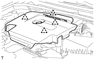
Hold the rear of the cover and slowly raise it to detach the clip on the rear of the cover. Continue to raise the cover to detach the 3 clips on the front and side of the cover and remove the cover.
Note
Attempting to disengage both front and rear clips at the same time may cause the cover to break.
-
-
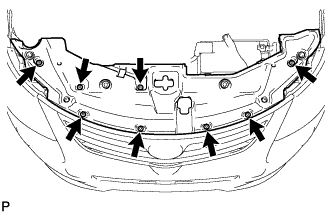
REMOVE FRONT LOWER BUMPER ABSORBER
-
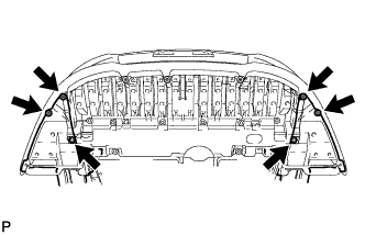
Remove the 4 screws and 2 bolts.
-
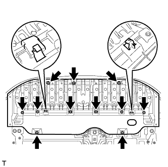
Remove the 8 bolts and 3 screws.
-
Detach the 2 hooks of the front lower bumper absorber from the installation holes on the body and remove the front lower bumper absorber.
-
-
REMOVE NO. 1 ENGINE UNDER COVER
-
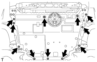
Remove the 11 clips the engine under cover.
-
-
REMOVE CENTER NO. 4 ENGINE UNDER COVER
-
Remove the 2 clips and under cover.
-
-
REMOVE NO. 2 ENGINE UNDER COVER
-
Remove the 4 clips and No. 2 engine under cover.
-
-
REMOVE REAR ENGINE UNDER COVER RH
-
Remove the 5 clips and under cover.
-
-
REMOVE REAR ENGINE UNDER COVER LH
-
Remove the 5 clips and under cover.
-
-
DRAIN ENGINE COOLANT
-
Loosen the radiator drain cock plug.
Tech Tips
Collect the coolant in a container and dispose of it according to the regulations in your area.
-
Remove the radiator reservoir cap.
CAUTION:
Do not remove the radiator reservoir cap and air release plug while the engine and radiator are still hot. Pressurized, hot engine coolant and steam may be released and cause serious burns.
-
Loosen the cylinder block drain cock plug. Then drain the coolant from the engine.
Tech Tips
The plug is on the backside of the generator on the EGR cooler side.
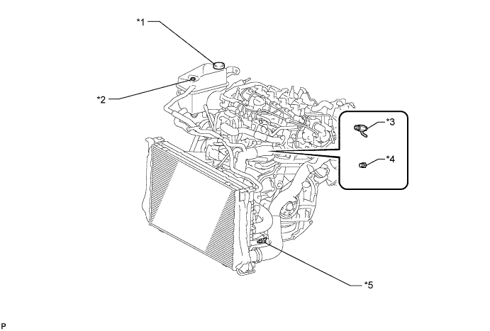
Text in Illustration *1 Radiator Reservoir Cap *2 Air Release Plug *3 Cylinder Block Drain Cock Plug (Type A) *4 Cylinder Block Drain Cock Plug (Type B) *5 Radiator Drain Cock Plug - -
-
-
DRAIN ENGINE OIL
-
Remove the oil filler cap.
-
Remove the oil pan drain plug and gasket, and then drain the engine oil into a container.
-
Install a new gasket and the oil pan drain plug.
- Torque:
- 38 N*m { 387 kgf*cm, 28 ft.*lbf }
-
-
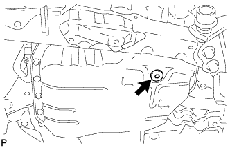
DRAIN MANUAL TRANSAXLE OIL (for Manual Transaxle)
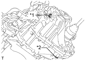
Text in Illustration *1 Filler Plug *2 Drain Plug
-
Remove the filler plug and gasket.
-
Remove the drain plug and gasket to drain the manual transaxle oil.
-
Install a new gasket and the drain plug.
- Torque:
- 39 N*m { 400 kgf*cm, 29 ft.*lbf }
-
-
DRAIN AUTOMATIC TRANSAXLE FLUID (for Automatic Transaxle)
-
Remove the refill plug and gasket from the automatic transaxle.
-
Using a 6 mm socket hexagon wrench, remove the overflow plug and gasket from the automatic transaxle.
-
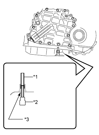
Using a 6 mm socket hexagon wrench, remove the No. 1 transmission oil filler tube from the automatic transaxle and drain the automatic transaxle fluid.
-
Using a 6 mm socket hexagon wrench, install the No. 1 transmission oil filler tube to the automatic transaxle.
- Torque:
- 1.7 N*m { 17 kgf*cm, 15 in.*lbf }
Text in Illustration *1 No. 1 Transmission Oil Filler Tube *2 Hexagon Socket Wrench *3 Overflow Plug Hole -
Using a 6 mm socket hexagon wrench, install a new gasket and the overflow plug to the automatic transaxle.
- Torque:
- 40 N*m { 408 kgf*cm, 30 ft.*lbf }
-
Temporarily install the gasket and the refill plug to the automatic transaxle.
-
-
REMOVE FRONT EXHAUST PIPE ASSEMBLY
-
Remove the front exhaust pipe Click here.
-
-
REMOVE BATTERY CLAMP SUB-ASSEMBLY
-
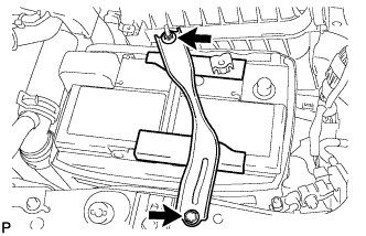
Remove the bolt and loosen the nut.
-
Detach the hook of the battery clamp from the battery carrier, and then remove the battery clamp.
-
-
REMOVE BATTERY
-
REMOVE BATTERY TRAY
-
REMOVE BATTERY CARRIER
-
Detach the 2 clamps and disconnect the wire harness.
-
Remove the 4 bolts and battery carrier.
-
-
REMOVE RADIATOR ASSEMBLY (for Automatic Transaxle)
-
Remove the radiator Click here.
-
-
REMOVE OIL COOLER TUBE SUB-ASSEMBLY (for Automatic Transaxle)
-
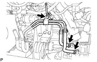
Disconnect the 2 hoses.
-
Remove the bolt and oil cooler tube.
-
-
DISCONNECT NO. 2 VACUUM TRANSMITTING HOSE ASSEMBLY
-
Disconnect the No. 2 vacuum transmitting hose from the intake manifold.
-
-
REMOVE NO. 3 AIR HOSE
-
Loosen the 2 hose clamps.
-
Remove the No. 3 air hose from the No. 2 air tube and diesel throttle body.
-
-
REMOVE AIR CLEANER CAP SUB-ASSEMBLY
-
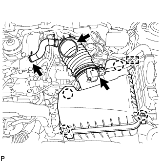
Detach the clamp and disconnect the mass air flow meter connector.
-
Disconnect the No. 2 ventilation hose.
-
Disconnect the air cleaner hose.
-
Detach the 4 clamps and remove the air cleaner cap.
-
-
REMOVE AIR CLEANER FILTER ELEMENT SUB-ASSEMBLY
-
REMOVE AIR CLEANER CASE
-
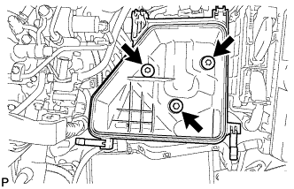
Remove the 3 bolts and air cleaner case.
-
-
REMOVE FUEL FILTER ASSEMBLY (w/o Combustion Type Power Heater)
-
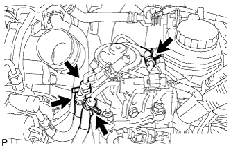
Disconnect the 4 fuel hoses.
-
Disconnect the level warning switch connector.
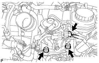
-
Remove the 2 nuts and fuel filter assembly.
-
-
REMOVE FUEL FILTER ASSEMBLY (w/ Combustion Type Power Heater)
-
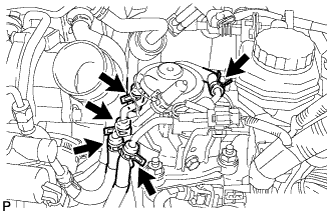
Disconnect the 5 fuel hoses.
-
Disconnect the level warning switch connector.
-
Remove the 2 nuts and fuel filter assembly.
-
-
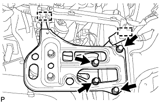
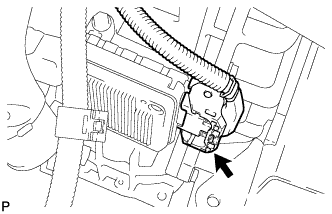
REMOVE FUEL FILTER SUPPORT
-
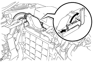
Raise the lever while pushing the lock on the lever, and disconnect the ECM connector.
Note
After disconnecting the connector, make sure that dirt, water or other foreign matter does not contact the connecting parts of the connector.
-
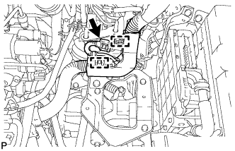
Disconnect the connector.
-
Detach the 2 clamps and disconnect the engine wire.
-
Remove the bolt and disconnect the glow relay.
-
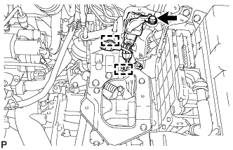
Detach the 2 clamps and disconnect the wire harness.
-
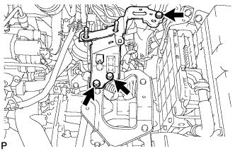
Remove the 3 bolts and fuel filter support.
-
-
REMOVE AIR CLEANER BRACKET
-
Remove the 3 bolts and air cleaner bracket.
-
-
DISCONNECT HOSES AND CONNECTORS
-
Remove the engine room No. 1 relay block cover.
-
Disconnect the current sensor connector.
-
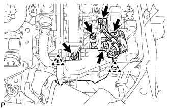
Disconnect the 3 connectors.
-
Remove the 2 nuts.
-
Detach the 2 claws and remove the engine room No. 1 relay block.
-
for Automatic Transaxle:
Disconnect the TCM connector.
-
for Manual Transaxle:
Detach the 4 clamps and disconnect the wire harness.
-
for Automatic Transaxle:
Detach the clamp, remove the bolt and disconnect the ground cable.
-
Disconnect the 2 fuel hoses.
-
for Manual Transaxle:
Remove the bolt and disconnect the ground cable.
-
Disconnect the vacuum pump hose.
-
-
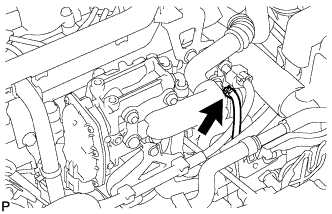
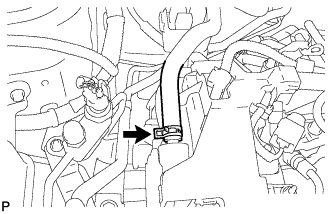
DISCONNECT INLET HEATER WATER HOSE
-
Disconnect the inlet heater water hose.
-
-
DISCONNECT OUTLET HEATER WATER HOSE
-
Disconnect the outlet heater water hose.
-
-
DISCONNECT NO. 1 RADIATOR HOSE (for Manual Transaxle)
-
Disconnect the No. 1 radiator hose.
-
-
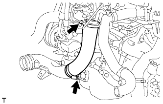
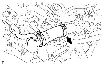
REMOVE INTERCOOLER AIR HOSE (for Manual Transaxle)
-
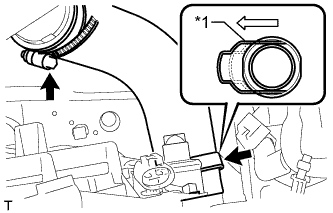
Text in Illustration *1 Retainer Disconnect the intercooler air hose from the No. 1 air tube.
-
Pull out the retainer and remove the intercooler air hose from the intercooler.
-
-
DISCONNECT WATER BY-PASS HOSE
-
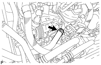
Disconnect the water by-pass hose.
-
-
DISCONNECT NO. 2 RADIATOR HOSE (for Manual Transaxle)
-
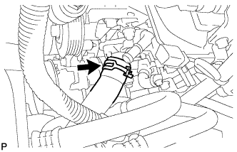
Disconnect the No. 2 radiator hose.
-
-
REMOVE INJECTOR DRIVER (for Manual Transaxle)
-
Detach the clamp and disconnect the 4 connectors.
-
Remove the 3 screws and injector driver.
-
-
REMOVE FRONT SUSPENSION MEMBER REINFORCEMENT RH
-
Remove the 4 bolts and front suspension member reinforcement.
-
-
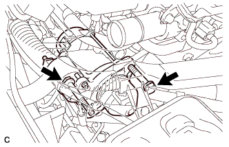
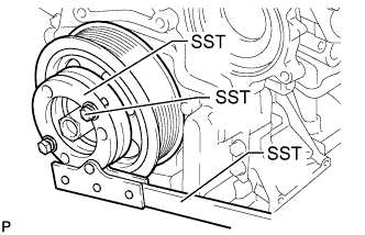
REMOVE FAN AND GENERATOR V BELT
-
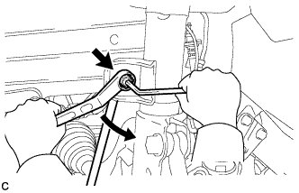
Using SST and a 22 mm wrench, rotate the tensioner pulley counterclockwise to loosen the belt tension. Then remove the belt.
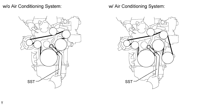
- SST
- 09216-42010
CAUTION:
-
Be careful as the wrench only fits loosely on the belt tensioner tool set point. The wrench may come off the set point and cause injuries.
-
Be careful that your hands do not become jammed between parts such as the belt, pulleys, etc.
Note
Make sure SST is installed as shown in the illustration. If not, SST and/or the belt may not be able to be removed.
-
-
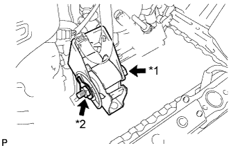
DISCONNECT COMPRESSOR WITH PULLEY ASSEMBLY (w/ Air Conditioning System)
-
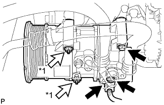
Disconnect the connector.
-
Remove the 2 bolts and 2 nuts.
Text in Illustration *1 Nut -
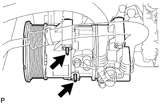
Using an E8 "TORX" socket wrench, remove the 2 stud bolts and disconnect the compressor.
Tech Tips
It is not necessary to completely remove the compressor. With the hoses connected to the compressor, hang the compressor on the vehicle body with a rope.
-
-
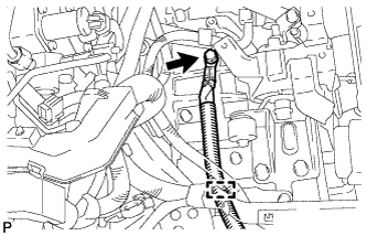
DISCONNECT TRANSMISSION CONTROL CABLE ASSEMBLY (for Manual Transaxle)
-
Remove the 2 pins and disconnect the 2 cables from the transaxle.
-
Remove the 2 clips and disconnect the 2 cables from the control cable bracket.
-
-
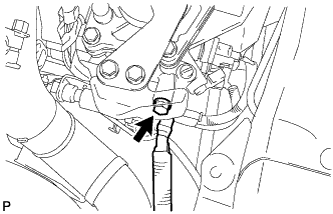
DISCONNECT TRANSMISSION CONTROL CABLE ASSEMBLY (for Automatic Transaxle)
-
Remove the nut and clip, and disconnect the transmission control cable.
-
-
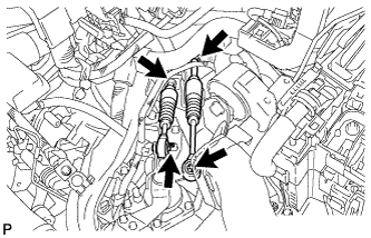
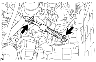
DISCONNECT CLUTCH RELEASE CYLINDER ASSEMBLY (for Manual Transaxle)
-
Remove the 6 bolts and disconnect the release cylinder and flexible hose bracket.
-
-
SECURE STEERING WHEEL
-
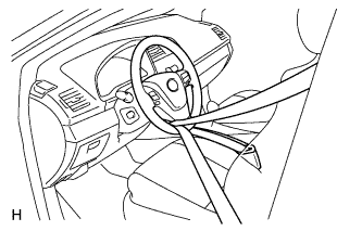
Secure the steering wheel with the seat belt in order to prevent rotation.
Tech Tips
This operation is useful to prevent damage to the spiral cable.
-
-
REMOVE COLUMN HOLE COVER SILENCER SHEET
-
Fold back the floor carpet, and remove the 2 clips and then column hole cover silencer sheet.
-
-
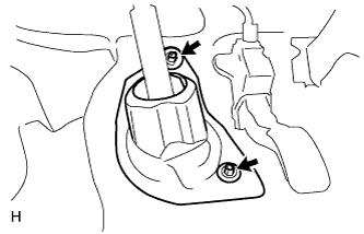
DISCONNECT NO. 2 STEERING INTERMEDIATE SHAFT ASSEMBLY
-
Remove the bolt.
Note
Do not disconnect the No. 2 steering intermediate shaft assembly from the steering intermediate shaft.
-
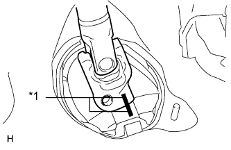
Text in Illustration *1 Matchmark Put matchmarks on the No. 2 steering intermediate shaft assembly and steering intermediate shaft.
-
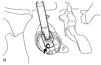
Disconnect the No. 2 steering intermediate shaft assembly from the steering intermediate shaft.
-
-
REMOVE NO. 1 STEERING COLUMN HOLE COVER SUB-ASSEMBLY
-
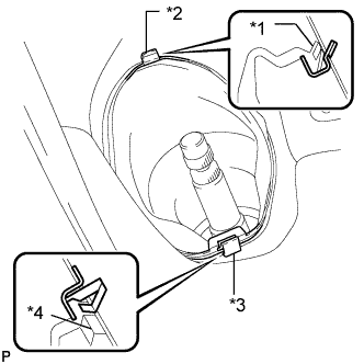
Remove clip A and the No. 1 steering column hole cover and detach clip B from the body.
Note
Do not damage clip A or B.
Text in Illustration *1 Lip *2 Clip B *3 Clip A *4 Lip
-
-
REMOVE FRONT AXLE SHAFT NUT LH
-
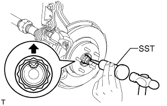
Using SST and a hammer, unstake the staked part of the front axle shaft nut.
- SST
- 09930-00010
Note
Loosen the staked part of the front axle shaft nut completely, otherwise the screw of the drive shaft may be damaged.
-
While applying the brakes, remove the front axle shaft nut.
-
-
REMOVE FRONT AXLE SHAFT NUT RH
Tech Tips
Perform the same procedure as for the LH side.
-
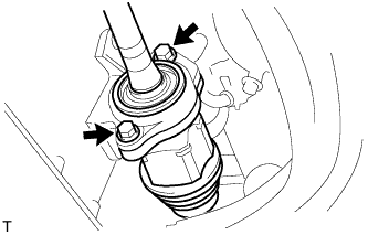
DISCONNECT FRONT STABILIZER LINK ASSEMBLY LH
-
Remove the nut and disconnect the stabilizer link assembly from the front shock absorber with coil spring.
Tech Tips
If the ball joint turns together with the nut, use a 6 mm hexagon wrench to hold the stud bolt.
-
-
DISCONNECT FRONT STABILIZER LINK ASSEMBLY RH
Tech Tips
Perform the same procedure as for the LH side.
-
REMOVE FRONT AXLE ASSEMBLY LH
-
Remove the front axle assembly LH Click here.
-
-
REMOVE FRONT AXLE ASSEMBLY RH
Tech Tips
Use the same procedures described for the LH side.
-
REMOVE FRONT DRIVE SHAFT ASSEMBLY LH
-
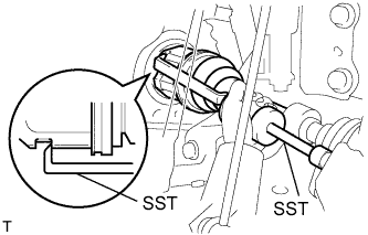
Using SST, remove the front drive shaft.
- SST
- 09520-00031
- 09520-01010
Note
-
Be careful not to damage the transaxle case oil seal, inboard joint boot or drive shaft dust cover.
-
Be careful not to drop the drive shaft.
-
-
REMOVE FRONT DRIVE SHAFT ASSEMBLY RH
-
Remove the 2 bolts and pull out the drive shaft together with the drive shaft bearing case.
-
Remove the drive shaft from the transaxle.
Note
-
Be careful not to damage the inboard joint boot and drive shaft dust cover.
-
Be careful not to drop the drive shaft.
-
-
-
REMOVE FRONT SUSPENSION MEMBER REINFORCEMENT LH
-
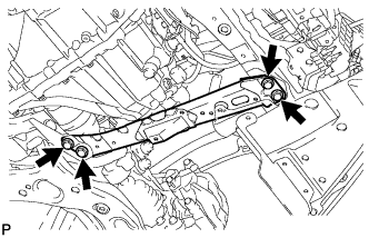
Remove the 4 bolts and front suspension member reinforcement LH.
-
-
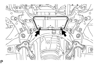
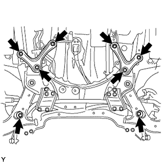
REMOVE FRONT CROSSMEMBER SUB-ASSEMBLY
-
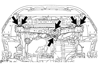
Remove the 6 bolts and front crossmember.
-
-
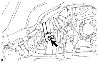
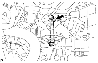
REMOVE FRONT ENGINE MOUNTING INSULATOR
-
Text in Illustration *1 Through Bolt *2 Nut Remove the through bolt, nut and front engine mounting insulator.
-
-
REMOVE ENGINE WITH TRANSAXLE
-
Remove the bolt and disconnect the cable bracket.
-
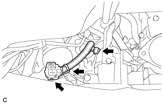
Detach the 3 clamps and disconnect the wire harness.
-
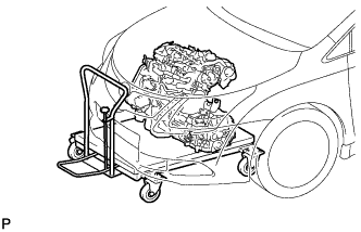
Set an engine lifter underneath the engine.
Tech Tips
Place the engine on wooden blocks or equivalent so that the engine is level.
-
Remove the 2 bolts and 2 nuts, and disconnect the engine mounting insulator RH.
-
Remove the bolt and nut and disconnect the engine mounting insulator LH.
-
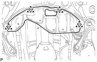
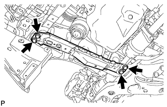
Remove the 6 bolts and front suspension member rear brace RH and LH.
-
Remove the 2 bolts and suspension crossmember.
-
Carefully remove the engine with transaxle from the vehicle.
-
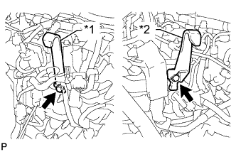
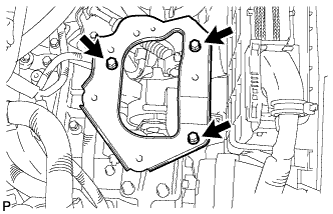
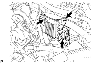
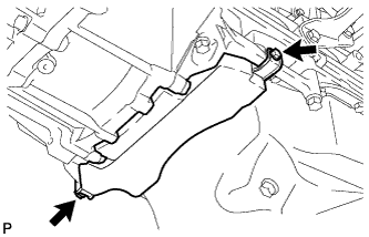
Text in Illustration *1 No. 1 Engine Hanger *2 No. 2 Engine Hanger Install 2 engine hangers with 2 bolts as shown in the illustration.
- Torque:
- 40 N*m { 408 kgf*cm, 30 ft.*lbf }
Tech Tips
Part No. No. 1 engine hanger 12281-26040 No. 2 engine hanger 12282-26010 Bolt 91552-81025 or 90105-W0042
-
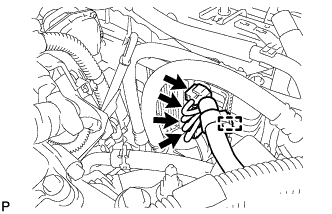
Insert the claw of the No. 1 engine hanger into the hole of the cylinder head.
-
Fit the fork part of the No. 2 engine hanger onto the rib of the cylinder head.
-
Attach an engine sling device and hang the engine with a chain block.
-
-
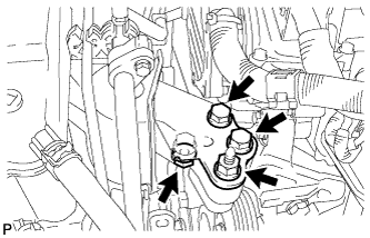
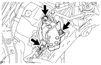
REMOVE REAR ENGINE MOUNTING INSULATOR
-
Remove the 3 bolts, 2 nuts and rear engine mounting insulator.
-
-
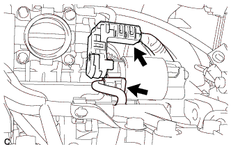
REMOVE NO. 1 AIR TUBE
-
Loosen the hose clamp, and remove the 2 bolts and No. 1 air tube.
-
-
REMOVE STARTER ASSEMBLY (for VALEO Made)
-
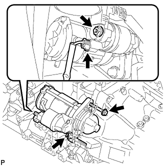
Disconnect the starter connector.
-
Open the terminal cap, remove the nut and disconnect the starter wire.
-
Remove the 2 bolts and starter.
-
-
REMOVE STARTER ASSEMBLY (for DENSO Made)
-
Disconnect the starter connector.
-
Open the terminal cap, remove the nut and disconnect the starter wire.
-
Remove the 2 bolts and starter.
-
-
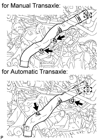
REMOVE ENGINE WIRE
-
Disconnect the connectors and clamps securing the engine wire to the engine, and then remove the bracket bolts and engine wire from the engine.
-
-
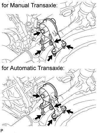
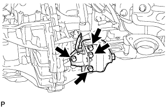
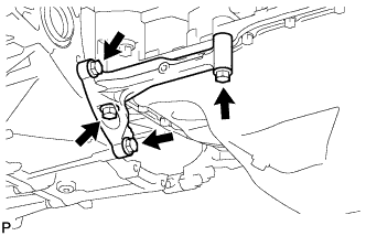
REMOVE FRONT ENGINE MOUNTING BRACKET (for Manual Transaxle)
-
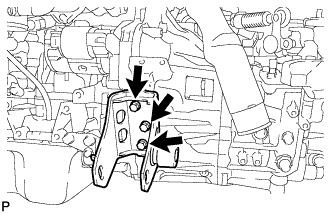
Remove the 3 bolts and front engine mounting bracket.
-
-
REMOVE FRONT ENGINE MOUNTING BRACKET (for Automatic Transaxle)
-
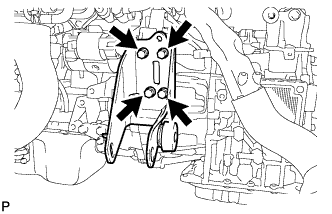
Remove the 4 bolts and front engine mounting bracket.
-
-
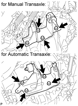
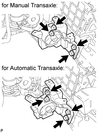
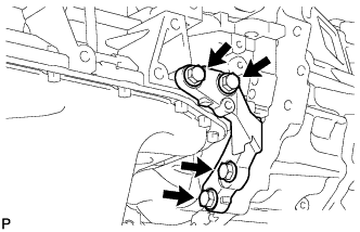
REMOVE REAR ENGINE MOUNTING BRACKET (for Manual Transaxle)
-
Remove the 5 bolts and rear engine mounting bracket.
-
-
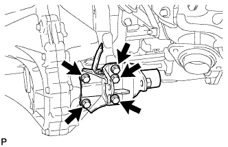
REMOVE REAR ENGINE MOUNTING BRACKET (for Automatic Transaxle)
-
Remove the 4 bolts and rear engine mounting bracket.
-
-
REMOVE ENGINE MOUNTING BRACKET LH
Tech Tips
Perform this procedure only when replacement of the engine mounting bracket is necessary.
-
Remove the 4 bolts and engine mounting bracket from the transaxle.
-
-
REMOVE ENGINE MOUNTING INSULATOR LH
Tech Tips
Perform this procedure only when replacement of the engine mounting insulator is necessary.
-
Remove the 4 bolts and engine mounting insulator from the body.
-
-
REMOVE ENGINE MOUNTING INSULATOR RH
Tech Tips
Perform this procedure only when replacement of the engine mounting insulator is necessary.
-
Remove the 3 bolts and engine mounting insulator from the body.
-
-
REMOVE OIL PAN INSULATOR
-
Remove the 2 bolts and oil pan insulator.
-
-
REMOVE STIFFENER PLATE RH
-
Remove the 4 bolts and stiffener plate RH.
-
-
REMOVE STIFFENER PLATE LH
-
Remove the 4 bolts and stiffener plate LH.
-
-
REMOVE MANUAL TRANSAXLE ASSEMBLY (for Manual Transaxle)
-
Remove the manual transaxle Click here.
-
-
REMOVE AUTOMATIC TRANSAXLE ASSEMBLY (for Automatic Transaxle)
-
Remove automatic transaxle Click here.
-
-
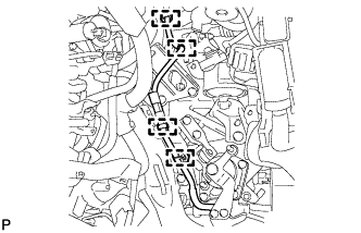
REMOVE CLUTCH COVER ASSEMBLY (for Manual Transaxle)
-
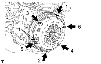
Text in Illustration *1 Matchmark Place matchmarks on the clutch cover and flywheel.
-
Loosen each set bolt 180° at a time until the spring tension is released.
Note
Be sure to uniformly loosen the bolts 180° at a time according to the order in the illustration.
-
Remove the set bolts and pull off the clutch cover to remove it.
Note
Do not drop the clutch disc.
-
-
REMOVE CLUTCH DISC ASSEMBLY (for Manual Transaxle)
Note
Keep the lining part of the clutch disc, the pressure plate, and the surface of the flywheel away from oil and foreign matter.
-
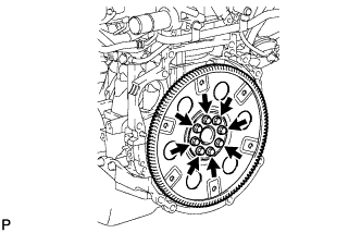
REMOVE FLYWHEEL SUB-ASSEMBLY (for Manual Transaxle)
-
Hold the crankshaft pulley with SST.
- SST
- 09213-58014 ( 91551-80840 )
- 09330-00021
-
Using a T55 "TORX" socket wrench, remove the 8 bolts and flywheel.
-
-
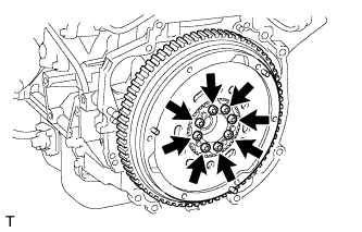
REMOVE DRIVE PLATE AND RING GEAR SUB-ASSEMBLY (for Automatic Transaxle)
-
Remove the 8 bolts, rear drive plate spacer, drive plate and ring gear, and front drive plate spacer.
-
-
INSTALL ENGINE TO ENGINE STAND
-
Install the engine to an engine stand, and remove the sling device and chain block from the engine.
-
Remove the 2 bolts and No. 1 and No. 2 engine hangers.
-