CAMSHAFT INSTALLATION

Note
-
When replacing the injectors (including shuffling the injectors between the cylinders), common rail, intake manifold or cylinder head, it is necessary to replace the injection pipes with new ones.
-
When replacing the fuel supply pump, common rail, intake manifold or cylinder head, it is necessary to replace the fuel inlet pipe with a new one.
-
INSPECT VALVE LASH ADJUSTER ASSEMBLY
Note
-
Keep the lash adjuster free from dirt and foreign objects.
-
Use only clean engine oil.
-
Place the lash adjuster into a container full of new engine oil.
-
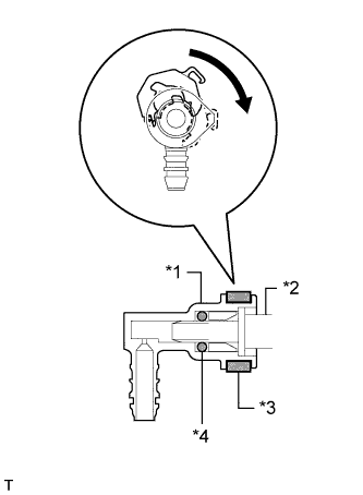
Insert SST tip into the lash adjuster plunger and use the tip to press down on the check ball inside the plunger.
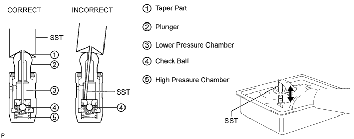
- SST
- 09276-75010
-
Squeeze SST and the lash adjuster together to move the plunger up and down 5 to 6 times.
-
Check the movement of the plunger and bleed air.
OK Plunger moves up and down. Note
When bleeding high-pressure air from the compression chamber, make sure that the tip of SST is actually pressing the check ball as shown in the illustration. If the check ball is not pressed, air will not bleed.
-
After bleeding air, remove SST. Then quickly and firmly press the plunger repeatedly with your fingers.
OK Plunger can be pressed 3 times. If the plunger can still be compressed after pressing it 3 times, replace the lash adjuster with a new one.
-
-
INSTALL VALVE LASH ADJUSTER ASSEMBLY
-
Install the 16 valve lash adjusters.
Note
Install the lash adjusters to their original positions.
-
-
INSTALL NO. 1 VALVE ROCKER ARM SUB-ASSEMBLY
-
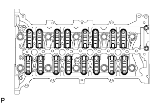
Install the 16 rocker arms to the lash adjusters.
-
-
INSTALL CAMSHAFT
-
Install the No. 2 bearing cap.
-
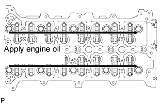
Apply clean engine oil to the cam of each camshaft, journals of the cylinder head and valve rocker arms.
-
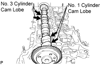
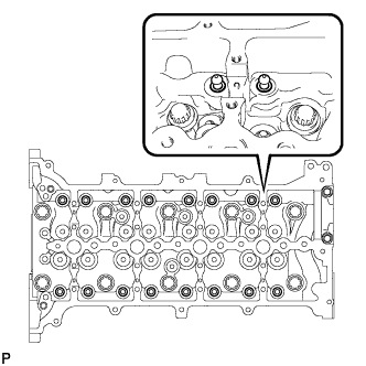
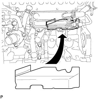
Place the No. 2 camshaft on the camshaft carrier as shown in the illustration so that the No. 1 and No. 3 cylinder cam lobes face upward.
Note
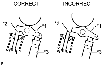
Before and after setting the camshaft and No. 2 camshaft on the engine, check that the rocker arm is firmly set to the lash adjuster.
Text in Illustration *1 Rocker Arm *2 Valve Stem *3 Lash Adjuster -
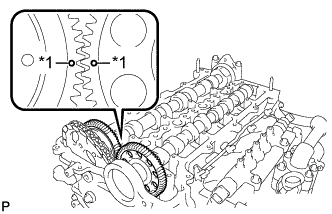
Text in Illustration *1 Dot Mark Align the camshaft and No. 2 camshaft timing mark (1 dot mark each).
-
Place the camshaft on the camshaft carrier.
-
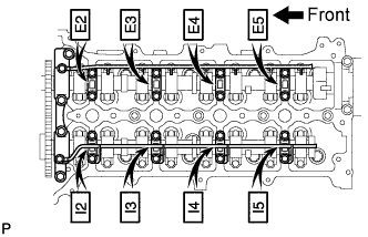
Set the camshaft bearing caps on the camshafts as shown in the illustration.
Tech Tips
Make sure of the marks and numbers on the camshaft bearing caps and place them in the proper position and direction.
-
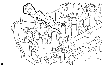
Set the oil delivery pipes on the camshaft bearing caps.
-
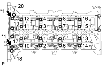
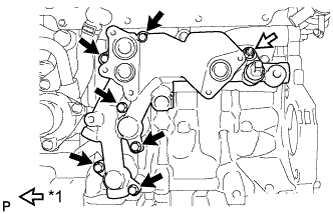
Text in Illustration *1 Union Bolt Temporarily install the 2 union bolts and 20 bolts.
-
Uniformly tighten the bolts in several steps, in the sequence shown in the illustration.
- Torque:
- for 1 to 16
- 10 N*m { 102 kgf*cm, 7 ft.*lbf }
- for 17 to 20
- 21 N*m { 214 kgf*cm, 15 ft.*lbf }
-
Tighten the 2 union bolts.
- Torque:
- 17 N*m { 173 kgf*cm, 13 ft.*lbf }
-
-
INSTALL CAMSHAFT TIMING SPROCKET
-
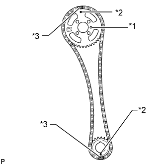
Text in Illustration *1 Straight Pin *2 Timing Mark *3 Yellow Paint Mark Install the crankshaft timing sprocket and camshaft timing sprocket to the chain so that the timing marks of the sprockets and paint marks of the chain are aligned.
-
Install the camshaft timing sprocket to the No. 2 camshaft by fitting the straight pin of the No. 2 camshaft into the hole on the camshaft timing sprocket.
-
Install the crankshaft timing sprocket to the crankshaft.
-
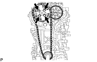
While holding the hexagon portion of the No. 2 camshaft, install and uniformly tighten the 4 bolts of the No. 2 camshaft.
- Torque:
- 20 N*m { 204 kgf*cm, 15 ft.*lbf }
-
-
INSTALL OIL PUMP DRIVE GEAR
-
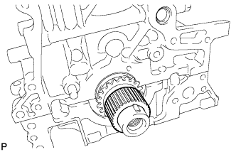
Install the oil pump drive gear to the crankshaft.
-
-
INSTALL NO. 1 CHAIN VIBRATION DAMPER
-
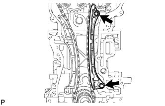
Install the No. 1 chain vibration damper with the 2 bolts.
- Torque:
- 21 N*m { 214 kgf*cm, 15 ft.*lbf }
-
-
INSTALL CHAIN TENSIONER SLIPPER
-
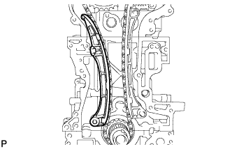
Install the chain tensioner slipper.
-
-
INSTALL NO. 1 CHAIN TENSIONER ASSEMBLY
-
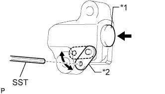
Text in Illustration *1 Plunger *2 Stopper Plate Move the stopper plate upward to release the lock, and push the plunger deep into the tensioner.
-
Move the stopper plate downward to set the lock, and insert SST into the stopper plate hole.
- SST
- 09240-00020 ( 09242-00200 )
-
Install the chain tensioner with the 2 bolts.
- Torque:
- 9.0 N*m { 92 kgf*cm, 80 in.*lbf }
-
Remove SST.
-
-
INSTALL SUPPLY PUMP ASSEMBLY
-
Install a new O-ring to the supply pump.
-
Install the supply pump drive coupling.
Tech Tips
Line up the coupling with the groove in the camshaft end.
Note
When reusing the coupling, it must be installed in the same orientation (top/bottom, front/back) as when it was removed,
-
Install the supply pump with the 2 bolts.
- Torque:
- 21 N*m { 209 kgf*cm, 15 ft.*lbf }
Tech Tips
Line up the end of the supply pump drive shaft with the supply pump drive coupling.
Note
Apply engine oil to the O-ring of the supply pump.
-
-
INSTALL TIMING CHAIN COVER SUB-ASSEMBLY
-
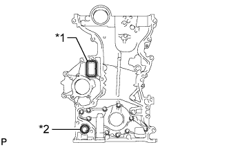
Text in Illustration *1 Gasket *2 O-Ring Install a new gasket and new O-ring to the timing chain cover.
-
Remove any old seal packing material.
-
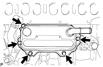
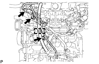
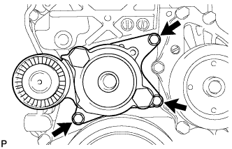
Apply seal packing in a continuous line to the timing chain cover as shown in the following illustration.
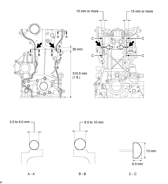
Seal packing Toyota Genuine Seal Packing Black, Three Bond 1207B or equivalent Apply Seal Packing as Follows Area Seal Packing Diameter (Round) Seal Packing Dimension (Flat) Seal Packing Application Length A - A 2.0 to 4.0 mm (0.0787 to 0.157 in.) - - B - B 8.0 to 10 mm (0.315 to 0.394 in.) - 30 mm (1.18 in.) C - C - 13 mm (0.512 in.) or more wide and 6.0 mm (0.236 in.) or more thick 15 mm (0.591 in.) Note
-
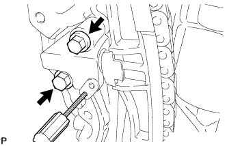
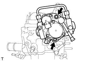
Be sure to clean and degrease the contact surfaces, especially the 4 areas indicated by the arrows in the illustration.
-
When the contact surfaces are wet, wipe them off with an oil-free cloth before applying seal packing.
-
When applying seal packing to area C - C, apply it in the direction of the white arrows in the illustration.
-
Install the timing chain cover within 3 minutes and tighten the bolts within 15 minutes after applying seal packing.
-
Do not start the engine for at least 4 hours after installation.
-
-
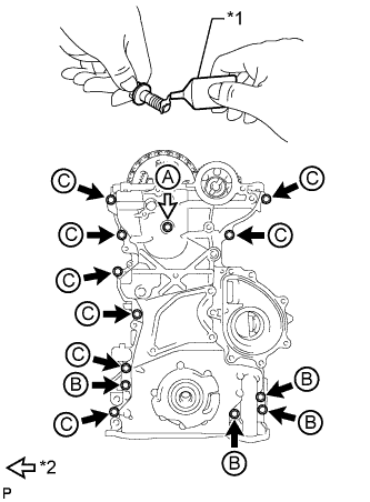
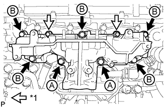
Text in Illustration *1 Adhesive *2 Bolt and New Seal Washer Apply adhesive to the 4 bolts labeled B.
Adhesive Toyota Genuine Adhesive 1324, Three Bond 1324 or equivalent -
Temporarily install the timing chain cover and a new seal washer with the 13 bolts.
Bolt Length Item Specified Condition Bolt A 60 mm (2.36 in.) Bolt B 30 mm (1.18 in.) Bolt C 30 mm (1.18 in.) Tech Tips
Bolt B and C are identical.
-
Tighten the 12 bolts labeled B and C.
- Torque:
- 23 N*m { 229 kgf*cm, 17 ft.*lbf }
-
Tighten the bolt labeled A.
- Torque:
- 21 N*m { 214 kgf*cm, 15 ft.*lbf }
-
-
INSTALL CRANKSHAFT PULLEY
-
Align the keyway of the pulley with the key located on the crankshaft, then slide the pulley into place to install it.
-
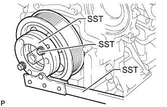
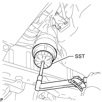
Using SST, install the pulley bolt.
- SST
- 09213-58014 ( 91551-80840 )
- 09330-00021
- Torque:
- 300 N*m { 3059 kgf*cm, 221 ft.*lbf }
-
-
INSTALL WATER PUMP ASSEMBLY
-
CONNECT CRANKSHAFT POSITION SENSOR WIRE HARNESS
-
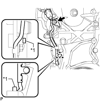
Text in Illustration *1 Protrusion Install the sensor wire harness with the bolt and clip.
- Torque:
- 8.8 N*m { 90 kgf*cm, 78 in.*lbf }
Note
Make sure the sensor wire harness is installed in the position shown in the illustration.
-
-
INSTALL CAMSHAFT POSITION SENSOR
-
Apply a light coat of engine oil to the O-ring of the sensor.
Note
Make sure that the O-ring is not cracked or jammed when installing the sensor.
-
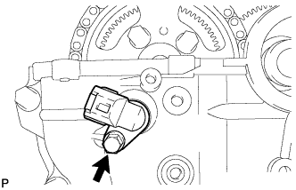
Install the sensor with the bolt.
- Torque:
- 8.8 N*m { 90 kgf*cm, 78 in.*lbf }
-
-
INSTALL OIL STRAINER SUB-ASSEMBLY
-
Install a new O-ring to the oil strainer.
-
Apply a light coat of engine oil to the O-ring.
-
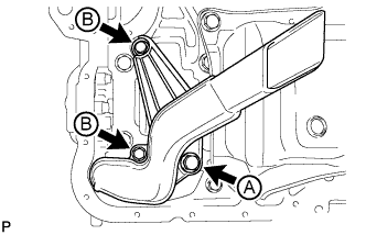
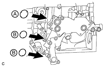
Install the oil strainer with the 3 bolts.
- Torque:
- for bolt A
- 42 N*m { 428 kgf*cm, 31 ft.*lbf }
- for bolt B
- 9.0 N*m { 92 kgf*cm, 80 in.*lbf }
-
-
INSTALL OIL FILTER BRACKET
-
Install a new gasket to the oil filter bracket.
-
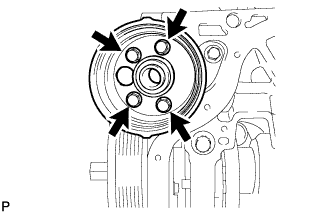
Install the oil filter bracket with the 4 bolts.
- Torque:
- 9.0 N*m { 92 kgf*cm, 80 in.*lbf }
-
-
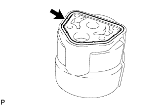
INSTALL OIL FILTER ELEMENT
-
Clean the inside of the oil filter cap, its threads and its O-ring groove.
-
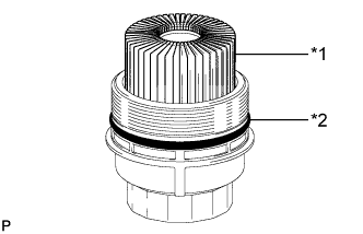
Text in Illustration *1 New Oil Filter Element *2 New O-Ring Apply a small amount of engine oil to a new O-ring and install it to the oil filter cap.
-
Set a new oil filter element in the oil filter cap.
-
Remove any dirt or foreign matter from the installation surface of the engine.
-
Apply a small amount of engine oil to the O-ring again and temporarily install the oil filter cap.
-
Using SST, tighten the oil filter cap.
- SST
- 09228-06501
- Torque:
- 40 N*m { 408 kgf*cm, 30 ft.*lbf }
-
-
INSTALL NO. 2 OIL PAN SUB-ASSEMBLY
-
Remove any old seal packing material.
-
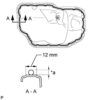
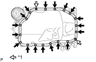
Apply seal packing in a continuous line as shown in the illustration.
Seal packing Toyota Genuine Seal Packing Black, Three Bond 1207B or equivalent Standard Seal Packing Dimension Area Seal Packing Diameter Acceptable Seal Packing Application Range A - A 4.0 to 7.0 mm (0.157 to 0.276 in.) 12 mm (0.472 in.) Note
-
Remove any oil from the contact surface.
-
Install the oil pan within 3 minutes and tighten the bolts within 10 minutes after applying seal packing.
-
Do not start the engine for at least 4 hours after installing.
-
-
Text in Illustration *1 Nut Install the oil pan with the 18 bolts and 2 nuts.
- Torque:
- 11 N*m { 107 kgf*cm, 8 ft.*lbf }
-
-
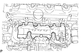
INSTALL CYLINDER HEAD COVER SUB-ASSEMBLY
-
Remove any old seal packing material.
-
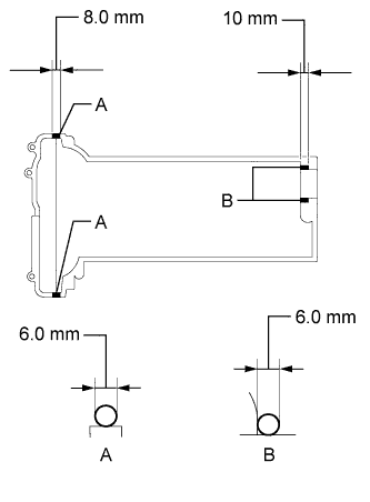
Apply seal packing to the cylinder head as shown in the illustration.
Seal packing Toyota Genuine Seal Packing Black, Three Bond 1207B or equivalent Standard Seal Packing Dimension Area Seal Packing Diameter Seal Packing Application Length A 6.0 mm (0.236 in.) 8.0 mm (0.315 in.) B 6.0 mm (0.236 in.) 10 mm (0.394 in.) -
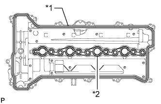
Text in Illustration *1 Cylinder Head Cover Gasket *2 No. 2 Cylinder Head Cover Gasket Install a new cylinder head cover gasket and new No. 2 cylinder head cover gasket to the cylinder head cover.
Note
Make sure the gaskets are not twisted and are not improperly seated on the cylinder head cover.
-
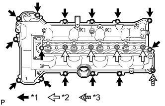
Text in Illustration *1 Bolt *2 Nozzle Holder Clamp Seat *3 Nut Install the cylinder head cover with the 4 nozzle holder clamp seats, 14 bolts and nut.
- Torque:
- for nozzle holder clamp seat
- 16 N*m { 167 kgf*cm, 12 ft.*lbf }
- for bolt and nut
- 11 N*m { 112 kgf*cm, 8 ft.*lbf }
-
-
INSTALL OIL FILLER CAP SUB-ASSEMBLY
-
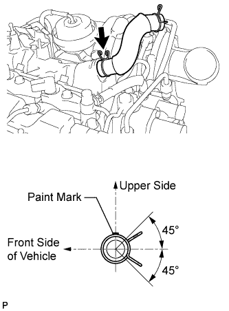
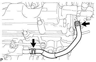
INSTALL VENTILATION HOSE
Tech Tips
The direction of the hose clamp is indicated in the illustration.
-
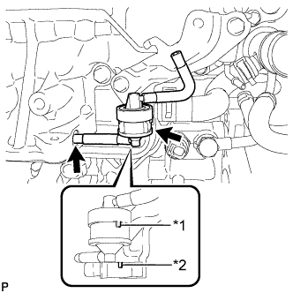
INSTALL VACUUM SWITCHING VALVE BRACKET
-
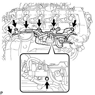
Install the vacuum switching valve bracket with the 5 bolts.
- Torque:
- 9.0 N*m { 92 kgf*cm, 80 in.*lbf }
-
Connect the 2 vacuum hoses.
-
-
INSTALL NO. 1 VACUUM TRANSMITTING PIPE SUB-ASSEMBLY
-
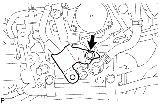
Install the No. 1 vacuum transmitting pipe with the bolt.
- Torque:
- 9.0 N*m { 92 kgf*cm, 80 in.*lbf }
-
Connect the 2 vacuum hoses.
-
-
INSTALL INJECTOR ASSEMBLY
Note
Before installing the injector, check for carbon, foreign matter, etc. on the seal surfaces of the cylinder head and injector. If there is foreign matter, remove it before installing the injector.
-
Install 4 new nozzle seats to the cylinder head.
-
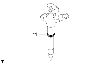
Text in Illustration *1 New O-Ring Install a new O-ring to each injector.
-
Apply a light coat of engine oil to the O-rings on each injector.
-
Install the 4 injectors to the cylinder head.
Note
Fit the injectors to the nozzle seats.
-
Text in Illustration *1 Washer Install the nozzle holder clamps and washers as shown in the illustration.
Note
Pay attention to the mounting orientation (beveled edge) of the washer.
-
Temporarily install the nozzle holder clamp bolts.
Note
When temporarily attaching the nozzle holder clamp and the nozzle holder clamp bolt, be careful not to position them at an angle.
Tech Tips
Apply a light coat of engine oil on the threads of the nozzle holder clamp bolts.
-
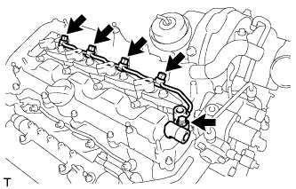
Temporarily install the 4 injection pipes.
-
Temporarily install the No. 1 leakage pipe with 4 new gaskets, the 4 union bolts and bolt.
-
Tighten the 4 nozzle holder clamp bolts.
- Torque:
- 25 N*m { 255 kgf*cm, 18 ft.*lbf }
-
-
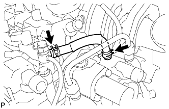
INSTALL NO. 1 NOZZLE LEAKAGE PIPE
-
Tighten the 4 union bolts.
- Torque:
- 18 N*m { 184 kgf*cm, 13 ft.*lbf }
-
Tighten the bolt.
- Torque:
- 21 N*m { 209 kgf*cm, 15 ft.*lbf }
-
-
INSTALL NO. 2 NOZZLE LEAKAGE PIPE
-
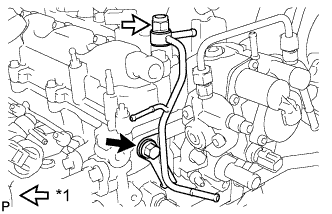
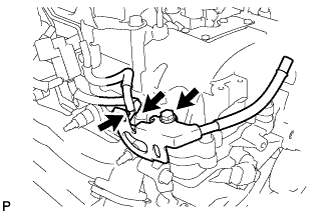
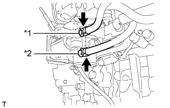
Text in Illustration *1 Check Valve Temporarily install the No. 2 nozzle leakage pipe and a new gasket with the check valve and bolt.
-
Tighten the check valve.
- Torque:
- 32 N*m { 321 kgf*cm, 23 ft.*lbf }
-
Tighten the bolt.
- Torque:
- 32 N*m { 321 kgf*cm, 23 ft.*lbf }
-
-
INSTALL NO. 3 FUEL HOSE
-
INSTALL NO. 2 FUEL PIPE (for CCo)
-
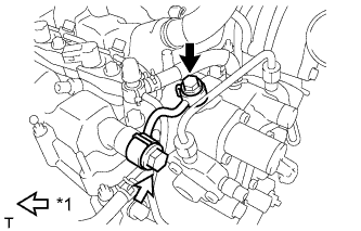
Text in Illustration *1 Check Valve Temporarily install the fuel pipe and 2 new gaskets with the check valve and union bolt.
-
Tighten the check valve.
- Torque:
- 32 N*m { 321 kgf*cm, 23 ft.*lbf }
-
Tighten the union bolt.
- Torque:
- 23 N*m { 235 kgf*cm, 17 ft.*lbf }
-
-
INSTALL FUEL TUBE SUB-ASSEMBLY (for DPF)
-

Text in Illustration *1 Check Valve Temporarily install the fuel tube and 2 new gaskets with the check valve and union bolt.
-
Tighten the check valve.
- Torque:
- 32 N*m { 321 kgf*cm, 23 ft.*lbf }
-
Tighten the union bolt.
- Torque:
- 23 N*m { 235 kgf*cm, 17 ft.*lbf }
-
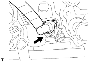
Connect the fuel tube connector to the injector.
-
Text in Illustration *1 Fuel Tube Connector *2 Injector *3 Retainer *4 O-Ring Turn the retainer in the direction indicated by the arrow until it makes a "click" sound.
Note
If the fuel tube connector is not inserted to the correct position on the injector, the retainer cannot be turned far enough in the direction of the arrow.
-
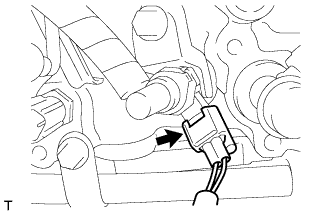
Connect the exhaust fuel addition injector connector.
-
-
INSTALL FUEL HOSE PROTECTOR (for DPF)
-
Install the fuel hose protector with the bolt.
- Torque:
- 21 N*m { 209 kgf*cm, 15 ft.*lbf }
-
-
INSTALL WATER INLET HOUSING
-

Install a new gasket and the inlet housing with the 3 nuts.
- Torque:
- 9.0 N*m { 92 kgf*cm, 80 in.*lbf }
-
-
INSTALL NO. 4 WATER BY-PASS HOSE
-
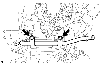
INSTALL NO. 2 WATER BY-PASS PIPE
-
Install the No. 2 water by-pass pipe with the 2 bolts.
- Torque:
- 11 N*m { 112 kgf*cm, 8 ft.*lbf }
-
-
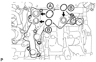
INSTALL NO. 1 OIL COOLER BRACKET
-
Apply engine oil to the 2 new O-rings labeled B in the illustration.
Note
Do not apply engine oil to the new O-ring labeled A in the illustration.
-
Install 3 new O-rings to the oil cooler bracket.
-
Text in Illustration *1 Nut Install the No. 1 oil cooler bracket with the 6 bolts and nut.
- Torque:
- 11 N*m { 112 kgf*cm, 8 ft.*lbf }
-
-
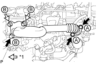
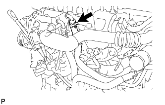
INSTALL NO. 1 TURBO OIL PIPE
-
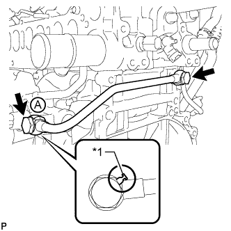
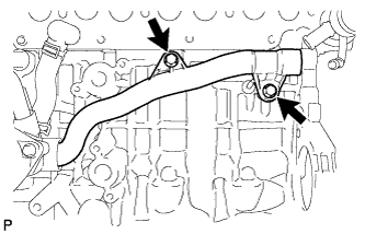
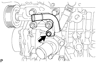
Text in Illustration *1 Gasket Install the No. 1 turbo oil pipe and 2 new gaskets with the 2 union bolts.
- Torque:
- 35 N*m { 357 kgf*cm, 26 ft.*lbf }
Note
Make sure the gasket of union bolt A contacts the No. 1 turbo oil pipe as shown in the illustration when tightening the union bolt.
-
-
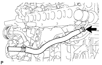
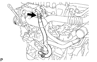
INSTALL NO. 3 WATER BY-PASS PIPE
-
Apply soapy water to a new O-ring and install it to the No. 3 water by-pass pipe.
-
Install the No. 3 water by-pass pipe with the 2 bolts.
- Torque:
- 21 N*m { 214 kgf*cm, 15 ft.*lbf }
-
-
INSTALL NO. 8 WATER BY-PASS HOSE
-
INSTALL NO. 6 WATER BY-PASS HOSE
-
INSTALL OIL COOLER ASSEMBLY
-
Apply engine oil to the 2 new O-rings labeled B in the illustration.
Note
Do not apply engine oil to the new O-ring labeled A in the illustration.
-
Install 3 new O-rings to the oil cooler bracket.
-
Install the oil cooler with the 5 bolts.
- Torque:
- 11 N*m { 112 kgf*cm, 8 ft.*lbf }
-
-
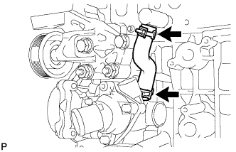
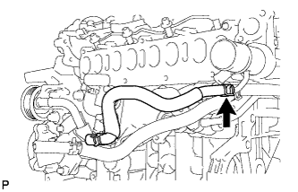
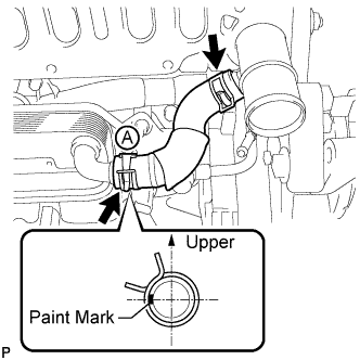
INSTALL WATER BY-PASS HOSE
Tech Tips
Make sure the claws of hose clamp A are positioned above the paint mark as shown in the illustration.
-
INSTALL NO. 1 CYLINDER BLOCK INSULATOR
-
Install the No. 1 cylinder block insulator to the cylinder block.
Note
Be sure to install the oil cooler before installing the No. 1 cylinder block insulator.
-
-
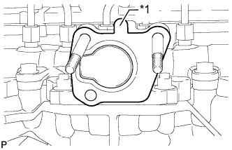
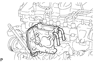
INSTALL INTAKE MANIFOLD
-
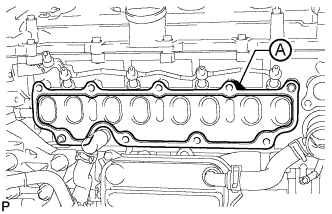
Install a new gasket to the cylinder head.
Tech Tips
Install the gasket with the part labeled A facing the right side of the vehicle as shown in the illustration.
-
Text in Illustration *1 Nut Install the intake manifold with the 7 bolts and 2 nuts.
- Torque:
- 23 N*m { 235 kgf*cm, 17 ft.*lbf }
Bolt Length Item Length Bolt A 90 mm (3.54 in.) Bolt B 25 mm (0.984 in.)
-
-
INSTALL NO. 2 INTAKE MANIFOLD
-
Install a new gasket and the No. 2 intake manifold with the bolt and 2 nuts.
- Torque:
- 24 N*m { 245 kgf*cm, 18 ft.*lbf }
-
-
INSTALL ENGINE COVER BRACKET
-
Install the engine cover bracket with the bolt.
- Torque:
- 20 N*m { 204 kgf*cm, 15 ft.*lbf }
-
-
INSTALL GAS FILTER BRACKET
-
Install the gas filter bracket with the 2 bolts.
- Torque:
- 8.8 N*m { 90 kgf*cm, 78 in.*lbf }
-
-
INSTALL NO. 1 GAS FILTER
-
Text in Illustration *1 Protrusion *2 Groove Install the No. 1 gas filter to the gas filter bracket.
Note
Make sure the protrusion of the No. 1 gas filter is aligned with the groove of the gas filter bracket.
-
Connect the vacuum hose.
-
-
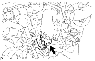
INSTALL DIESEL TURBO PRESSURE SENSOR
-
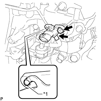
Text in Illustration *1 Protrusion Install the sensor with the bolt.
- Torque:
- 8.8 N*m { 90 kgf*cm, 78 in.*lbf }
Note
Make sure the protrusion of the gas filter bracket is inserted into the hole of the sensor.
-
Connect the vacuum hose.
-
-
INSTALL INTAKE MANIFOLD INSULATOR
-
Install the intake manifold insulator to the intake manifold.
-
-
INSTALL COMMON RAIL ASSEMBLY
-
Install the common rail with the 2 bolts.
- Torque:
- 21 N*m { 209 kgf*cm, 15 ft.*lbf }
-
-
INSTALL NO. 4 FUEL HOSE
-
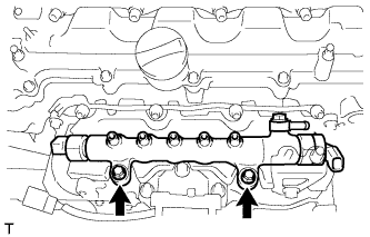
INSTALL INJECTION PIPE SUB-ASSEMBLY
-
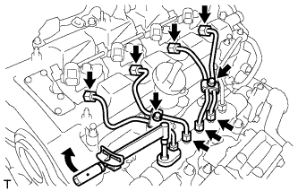
Using a 14 mm union nut wrench, tighten the 4 nuts at the common rail end of the injection pipes.
- Torque:
- 30 N*m { 306 kgf*cm, 22 ft.*lbf }
Note
Use the formula to calculate special torque values for situations where a union nut wrench is combined with a torque wrench Click here.
-
Using a 14 mm union nut wrench, tighten the 4 nuts at the injector end of the injection pipes.
- Torque:
- 30 N*m { 306 kgf*cm, 22 ft.*lbf }
Note
Use the formula to calculate special torque values for situations where a union nut wrench is combined with a torque wrench Click here.
-
Install the 4 injection pipe clamps with the 2 bolts.
- Torque:
- 5.0 N*m { 51 kgf*cm, 44 in.*lbf }
-
-
INSTALL FUEL INLET PIPE SUB-ASSEMBLY
-
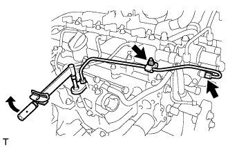
Temporarily install the fuel inlet pipe with the 2 clamps and nut.
-
Using a 14 mm union nut wrench, first tighten the nut at the common rail end of the fuel inlet pipe.
- Torque:
- 30 N*m { 306 kgf*cm, 22 ft.*lbf }
Note
Use the formula to calculate special torque values for situations where a union nut wrench is combined with a torque wrench Click here.
-
Using a 14 mm union nut wrench, tighten the nut at the supply pump end of the fuel inlet pipe.
- Torque:
- 30 N*m { 306 kgf*cm, 22 ft.*lbf }
Note
Use the formula to calculate special torque values for situations where a union nut wrench is combined with a torque wrench Click here.
-
Tighten the No. 2 injection pipe clamp nut.
- Torque:
- 5.0 N*m { 51 kgf*cm, 44 in.*lbf }
-
-
INSTALL ENGINE OIL LEVEL DIPSTICK GUIDE
-
Install a new O-ring to the engine oil level dipstick guide.
-
Install the engine oil level dipstick guide with the 2 bolts.
- Torque:
- 33 N*m { 337 kgf*cm, 24 ft.*lbf }
-
Connect the connector and attach the wire harness clamp to the engine oil level dipstick guide.
-
Install the engine oil level dipstick.
-
-
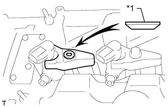
INSTALL ELECTRIC EGR CONTROL VALVE ASSEMBLY
-
Text in Illustration *1 Protrusion Install a new gasket.
Note
Make sure the protrusion of the gasket is facing upward as shown in the illustration.
-
Install the electric EGR control valve.
-
-
INSTALL NO. 2 EGR PIPE SUB-ASSEMBLY
-
Install a new gasket to the electric EGR control valve.
-
Text in Illustration *1 Nut Temporarily install the No. 2 EGR pipe with the 3 bolts and 2 nuts.
Bolt Length Item Specified Condition Bolt A 25 mm (0.984 in.) Bolt B 70 mm (2.76 in.) -
Tighten the 2 bolts labeled A shown in the illustration.
- Torque:
- 24 N*m { 245 kgf*cm, 18 ft.*lbf }
-
Tighten the bolt and 2 nuts labeled B shown in the illustration.
- Torque:
- 24 N*m { 245 kgf*cm, 18 ft.*lbf }
-
Connect the electric EGR control valve connector.
-
-
INSTALL EGR VALVE BRACKET
-
Install the 2 EGR valve brackets with the 3 bolts.
- Torque:
- 24 N*m { 245 kgf*cm, 18 ft.*lbf }
-
-
CONNECT NO. 8 WATER BY-PASS HOSE
-
INSTALL NO. 7 WATER BY-PASS HOSE
-
INSTALL DIESEL THROTTLE BODY ASSEMBLY
-
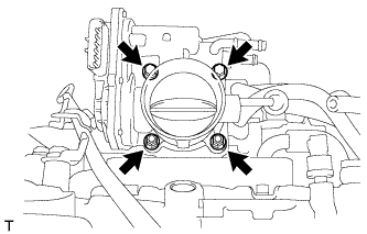
Install a new gasket and the diesel throttle body with the 2 bolts and 2 nuts.
- Torque:
- 11 N*m { 112 kgf*cm, 8 ft.*lbf }
-
Text in Illustration *1 No. 6 Water By-pass Hose *2 No. 7 Water By-pass Hose Connect the No. 6 and No. 7 water by-pass hoses.
-
-
INSTALL V-RIBBED BELT TENSIONER ASSEMBLY
-
Install the V-ribbed belt tensioner with the 3 bolts.
- Torque:
- 20 N*m { 204 kgf*cm, 15 ft.*lbf }
Note
As the heads of the bolts are not as thick as those of typical bolts, be careful not to damage them during installation.
-
-
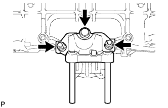
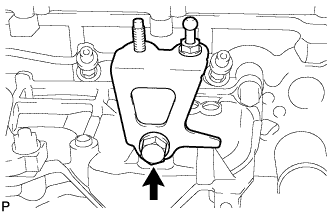
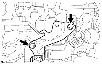
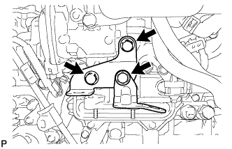
INSTALL ENGINE MOUNTING BRACKET
-
Temporarily install the engine mounting bracket with the 2 bolts labeled A.
-
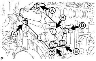
Temporarily install the 2 bolts and 2 nuts labeled B in the illustration.
-
Tighten the 2 bolts labeled A in the illustration.
- Torque:
- 28 N*m { 286 kgf*cm, 21 ft.*lbf }
-
Tighten the 2 bolts and 2 nuts labeled B in the illustration.
- Torque:
- 80 N*m { 816 kgf*cm, 59 ft.*lbf }
-
-
INSTALL NO. 4 WATER BY-PASS PIPE
-
Install a new O-ring to the No. 4 water by-pass pipe.
-
Install the No. 4 water by-pass pipe with the bolt.
- Torque:
- 11 N*m { 112 kgf*cm, 8 ft.*lbf }
-
-
INSTALL NO. 2 IDLER PULLEY SUB-ASSEMBLY
-
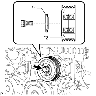
Text in Illustration *1 No. 2 Idler Pulley Cover Plate *2 No. 2 Idler Pulley Install the No. 2 idler pulley and No. 2 idler pulley cover plate with the bolt.
- Torque:
- 40 N*m { 408 kgf*cm, 30 ft.*lbf }
Note
Make sure the No. 2 idler pulley cover plate is facing the direction shown in the illustration.
-
-
INSTALL NO. 1 IDLER PULLEY SUB-ASSEMBLY
-
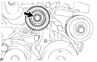
Install the No. 1 idler pulley with the bolt.
- Torque:
- 40 N*m { 408 kgf*cm, 30 ft.*lbf }
-
-
INSTALL IDLER PULLEY COVER PLATE
-
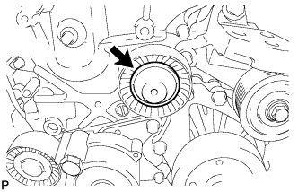
Install the idler pulley cover plate to the No. 1 idler pulley.
-
-
INSTALL VACUUM PUMP ASSEMBLY
-
Install the idler pulley cover plate to the No. 1 idler pulley.
-
-
INSTALL GENERATOR ASSEMBLY
-
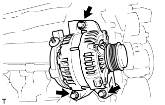
Install the generator with the 3 bolts.
- Torque:
- 25 N*m { 255 kgf*cm, 18 ft.*lbf }
-
-
CONNECT ENGINE WIRE
-
Connect the connectors and clamps, and then connect the engine wire to the engine with the bracket bolts.
-
-
INSTALL ENGINE ASSEMBLY
-
Install the engine assembly Click here.
-
-
CONNECT CABLE TO NEGATIVE BATTERY TERMINAL
Note
When disconnecting the cable, some systems need to be initialized after the cable is reconnected Click here.