ECD SYSTEM (for DPF), Diagnostic DTC:P200C, P200E, P2428

| DTC Code | DTC Name |
|---|---|
| P200C | Diesel Particulate Filter Over Temperature Bank 1 |
| P200E | Catalyst System Temperature Too High Bank 1 |
| P2428 | Exhaust Gas Temperature Too High Bank 1 |
DESCRIPTION
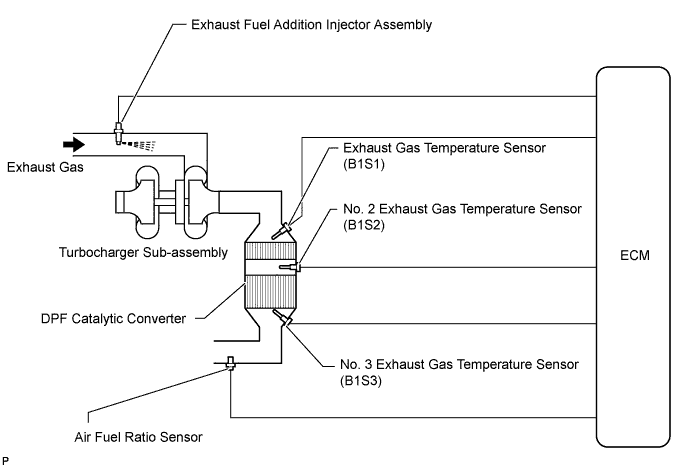
The exhaust fuel addition injector is mounted on the outlet of the turbocharger sub-assembly, and low pressure fuel is supplied to the injector by the feed pump in the supply pump. This injector adds fuel in response to a control signal from the ECM, in order to perform PM forced regeneration.
During PM forced regeneration, the exhaust fuel addition injector adds fuel to raise the DPF* catalyst temperature.
Tech Tips
-
For more information on the exhaust fuel addition injector and DPF, refer to the following procedures Click here.
-
If P200C, P200E and P2428 are present, refer to the diagnostic trouble code (DTC) chart for Diesel Particulate Filter System Click here.
*: Diesel Particulate Filter
| DTC Detection Drive Pattern | DTC Detection Condition | Trouble Area |
|---|---|---|
| PM forced regeneration* *: When P200C is detected due to a DPF catalyst problem such as thermal degradation, because the malfunction cannot be duplicated even if the vehicle is driven after PM forced regeneration is performed, perform troubleshooting by following the diagnosis procedure and checking the freeze frame data. |
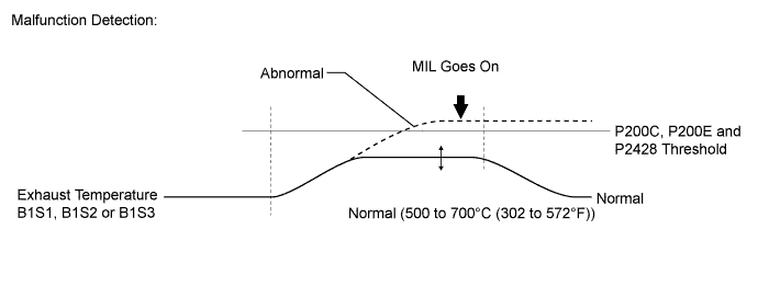
The value of "Exhaust Temperature B1S3" is higher than 1000°C (1832°F) for 5 seconds (1 trip detection logic). |
Main Trouble Area
Sub Trouble Area
Common Inspection Item: |
| DTC Detection Drive Pattern | DTC Detection Condition | Trouble Area |
|---|---|---|
| PM forced regeneration* *: When P200E is detected due to a DPF catalyst problem such as thermal degradation, because the malfunction cannot be duplicated even if the vehicle is driven after PM forced regeneration is performed, perform troubleshooting by following the diagnosis procedure and checking the freeze frame data. |
The value of "Exhaust Temperature B1S2" is higher than 1000°C (1832°F) for 5 seconds (1 trip detection logic). |
Main Trouble Area
Sub Trouble Area
Common Inspection Item: |
| DTC Detection Drive Pattern | DTC Detection Condition | Trouble Area |
|---|---|---|
| PM forced regeneration* *: When P2428 is detected due to a DPF catalyst problem such as thermal degradation, because the malfunction cannot be duplicated even if the vehicle is driven after PM forced regeneration is performed, perform troubleshooting by following the diagnosis procedure and checking the freeze frame data. |
The value of "Exhaust Temperature B1S1" is higher than 1000°C (1832°F) for 5 seconds (1 trip detection logic). |
Main Trouble Area
Sub Trouble Area
Common Inspection Item: |
Tech Tips
-
Due to fail-safe operation when other DTCs (that involve the engine power limit) are stored, PM forced regeneration may be prohibited.
This DTC or P20CF, P244B, P244C and P2463 may be stored due to the fact that PM forced regeneration is prohibited due to the fail-safe operation of other DTCs.
-
The air-fuel ratio and the exhaust gas temperature can be checked by entering the following menus on the intelligent tester: Powertrain / Engine and ECT / Data List / AF Lambda B1S1, Exhaust Temperature B1S1, Exhaust Temperature B1S2 and Exhaust Temperature B1S3.
-
Malfunctions in the engine itself may affect the DPF system control and cause storage of this DTC. For example, malfunctions in the injector assemblies that cause a large amount of smoke emission: These affect the exhaust fuel addition injector assembly operation. Blockages or leaks in the air intake system, or an EGR system malfunction such as EGR passage blockages: These malfunctions affect the DPF catalyst temperature control. Therefore, the engine condition itself should also be checked, in addition to the exhaust fuel addition injector assembly.
| DTC No. | Data List |
|---|---|
| P200C |
|
MONITOR DESCRIPTION
The ECM monitors DPF catalyst temperature. When the temperature becomes high due to uncombusted fuel, engine oil or thermal degradation to the DPF catalyst, the ECM illuminates the MIL.
INSPECTION PROCEDURE
Note
-
Inspect the fuses of circuits related to this system before performing the following inspection procedure.
-
After replacing the ECM, the new ECM needs registration Click here and initialization Click here.
-
After replacing the fuel supply pump assembly, the ECM needs initialization Click here.
-
After replacing an injector assembly, the ECM needs registration Click here.
Tech Tips
Read freeze frame data using the intelligent tester. Freeze frame data records the engine condition when malfunctions are detected. When troubleshooting, freeze frame data can help determine if the vehicle was moving or stationary, if the engine was warmed up or not, and other data from the time the malfunction occurred.
PROCEDURE
-
READ OUTPUT DTC (RECORD STORED DTC AND FREEZE FRAME DATA) (PROCEDURE 1)
-
Connect the intelligent tester to the DLC3.
-
Turn the ignition switch to ON and turn the tester on.
-
Enter the following menus: Powertrain / Engine and ECT / DTC.
-
Record the stored DTC and freeze frame data.
NEXT 
-
-
REPLACE EXHAUST GAS TEMPERATURE SENSOR
-
Check the values of "Exhaust Temperature B1S1", "Exhaust Temperature B1S2" and "Exhaust Temperature B1S3" that were saved in Procedure 1.
Result Result Items to be Replaced DTC P2428 is output and the value of "Exhaust Temperature B1S1" is 850°C (1562°F) or higher Exhaust gas temperature sensor (B1S1) DTC P200E is output and the value of "Exhaust Temperature B1S2" is 850°C (1562°F) or higher No. 2 exhaust gas temperature sensor (B1S2) DTC P200C is output and the value of "Exhaust Temperature B1S3" is 850°C (1562°F) or higher No. 3 exhaust gas temperature sensor (B1S3) -
If DTC P200C, P200E and/or P2428 is output, the exhaust gas temperature sensors need to be replaced. However, make sure to perform all diagnostic procedures for P200C, P200E and/or P2428 before replacing the exhaust gas temperature sensors.
Tech Tips
If the exhaust gas temperature sensors are subjected to an abnormally high temperature, the internal resistance of the sensor increases. This causes incorrect temperature measurement.
NEXT
-
-
CHECK FOR BLACK SMOKE
-
Start the engine and drive the vehicle until the engine coolant temperature reaches 60°C (140°F) or higher.
-
Stop the vehicle and allow the engine to idle.
-
Fully depress the accelerator pedal for 5 seconds, and then release it [A].
-
Repeat the above procedure [A] 10 times [B].
-
Check for black smoke emission during procedure [A] and [B].
OK Black smoke is emitted less than 5 times. Tech Tips
Even if the black smoke is very thin, count the number of black smoke emissions if there is any visible smoke.
OK 
CHECK FUEL INJECTION SYSTEM Click here
NG
REPLACE CATALYTIC CONVERTER Click here
-
-
REPLACE CATALYTIC CONVERTER
-
Even though it has been determined that the DPF catalytic converter (Exhaust manifold converter sub-assembly) needs to be replaced, make sure to perform all diagnostic procedures for DTC P200C, P200E and/or P2428 before replacing it.
Tech Tips
This DTC is stored because an excessive amount of PM has accumulated and resulted in abnormal combustion. It is necessary to diagnose the cause of abnormal PM accumulation and repair the problem. Therefore, do not perform replacement at this time.
NEXT
-
-
CHECK FUEL INJECTION SYSTEM
-
Check the fuel injection system Click here.
NEXT
-
-
CHECK INTAKE / EXHAUST SYSTEM
-
Check the intake/exhaust system Click here.
NEXT
-
-
CHECK AFTER TREATMENT CONTROL SYSTEM
-
Check the after treatment control system Click here.
NEXT
-
-
REPLACE MALFUNCTIONING PARTS
Tech Tips
Replace the following items only when it has been determined necessary based on diagnosis for DTC P200C, P200E and/or P2428.
-
Replace the DPF catalytic converter (Exhaust manifold converter sub-assembly) Click here.
Note
Perform Initialization procedure for DPF catalyst record clear Click here.
-
Replace the exhaust gas temperature sensor (B1S1) Click here.
-
Replace the No. 2 exhaust gas temperature sensor (B1S2) Click here.
-
Replace the No. 3 exhaust gas temperature sensor (B1S3) Click here.
NEXT
-
-
CONFIRM WHETHER MALFUNCTION HAS BEEN SUCCESSFULLY REPAIRED
-
Clear the DTC and Exhaust Fuel Addition FB value by disconnecting the cable from the negative (-) battery terminal or removing the EFI MAIN No. 2 fuse for 1 minute or more.
Tech Tips
-
The accumulated PM volume stored in the ECM cannot be initialized using the intelligent tester.
-
To perform PM forced regeneration, it is necessary to perform initialization of the accumulated PM volume stored in the ECM.
-
-
Connect the intelligent tester to the DLC3.
-
Start the engine and drive the vehicle until the engine coolant temperature reaches 60°C (140°F) or more.
-
Move the shift lever to N and set the parking brake.
-
Turn the tester on.
-
Enter the following menus: Powertrain / Engine and ECT / Active Test / Activate the DPF Rejuvenate (PM) / Data List / PM Accumulation Ratio.
-
Perform the Active Test while the vehicle is driven at a constant vehicle speed within 50 to 100 km/h (31 to 62 mph) (transmission in 3rd gear) for more than 15 minutes.
Tech Tips
-
While the "Activate the DPF Rejuvenate (PM)" Active Test is being performed, the accelerator opening angle should be kept as constant as possible.
-
When you start driving, "DPNR/DPF Status Reju (PM)" on the Data List displays "Compl". However, continue to drive the vehicle until "PM Accumulation Ratio" drops to 0%.
-
Once "PM Accumulation Ratio" drops to 0%, regeneration is complete.
-
-
Continue to drive the vehicle until "PM Accumulation Ratio" drops to 0%.
CAUTION:
Be aware of excessive heat on and around the exhaust pipes during PM forced regeneration.
Note
If PM forced regeneration stops, repair the malfunction that caused it to stop, and perform it again to complete the operation.
Tech Tips
-
PM forced regeneration completes in 15 to 40 minutes.
-
PM forced regeneration time changes depending on PM Accumulation Ratio and driving conditions.
-
A fail-safe stops PM forced regeneration if Catalyst Differential Press increases too much during regeneration
-
Exhaust Temperature B1S3 becomes 500°C (932°F) or more within 20 minutes of PM forced regeneration start.
-
PM forced regeneration will be stopped if the accelerator pedal is depressed during regeneration. In this case, PM forced regeneration needs to be performed again.
-
Even if PM forced regeneration stops while it is occurring, the intelligent tester displays Compl (complete) for DPNR/DPF Status Reju (PM).
-
NEXT 
END
-