ENGINE OIL COOLER INSTALLATION

Note
-
When replacing the injectors (including shuffling the injectors between the cylinders), common rail, intake manifold or cylinder head, it is necessary to replace the injection pipes with new ones.
-
When replacing the fuel supply pump, common rail, intake manifold or cylinder head, it is necessary to replace the fuel inlet pipe with a new one.
-
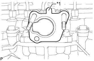
INSTALL OIL COOLER ASSEMBLY
-
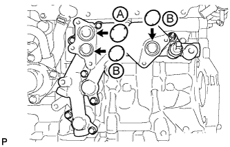
Apply engine oil to the 2 new O-rings labeled B in the illustration.
Note
Do not apply engine oil to the new O-ring labeled A in the illustration.
-
Install 3 new O-rings to the oil cooler bracket.
-
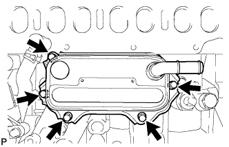
Install the oil cooler with the 5 bolts.
- Torque:
- 11 N*m { 112 kgf*cm, 8 ft.*lbf }
-
-
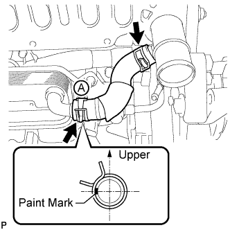
INSTALL WATER BY-PASS HOSE
Tech Tips
Make sure the claws of hose clamp A are positioned above the paint mark as shown in the illustration.
-
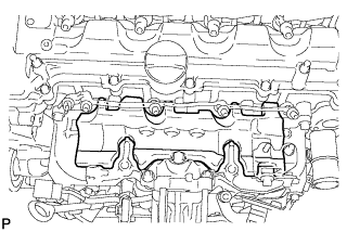
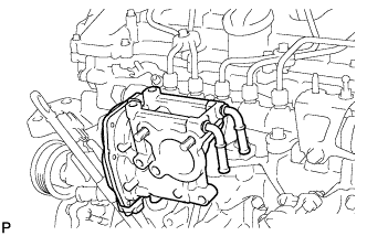
INSTALL INTAKE MANIFOLD
-
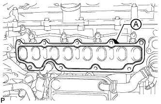
Install a new gasket to the cylinder head.
Tech Tips
Install the gasket with the part labeled A facing the right side of the vehicle as shown in the illustration.
-
Text in Illustration *1 Nut Install the intake manifold with the 7 bolts and 2 nuts.
- Torque:
- 23 N*m { 235 kgf*cm, 17 ft.*lbf }
Bolt Length Item Specified Condition Bolt A 90 mm (3.54 in.) Bolt B 25 mm (0.984 in.)
-
-
CONNECT NO. 2 VACUUM TRANSMITTING HOSE
-
Connect the No. 2 vacuum transmitting hose to the intake manifold.
-
-
INSTALL NO. 2 INTAKE MANIFOLD
-
Install a new gasket and the No. 2 intake manifold with the bolt and 2 nuts.
- Torque:
- 24 N*m { 245 kgf*cm, 18 ft.*lbf }
-
-
INSTALL ENGINE COVER BRACKET
-
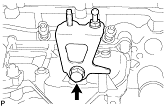
Install the engine cover bracket with the bolt.
- Torque:
- 20 N*m { 204 kgf*cm, 15 ft.*lbf }
-
-
INSTALL GAS FILTER BRACKET
-
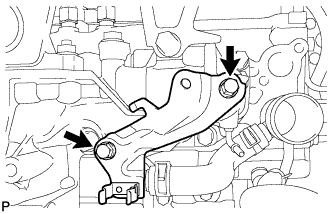
Install the gas filter bracket with the 2 bolts.
- Torque:
- 8.8 N*m { 90 kgf*cm, 78 in.*lbf }
-
-
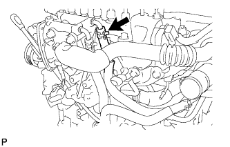
INSTALL NO. 1 GAS FILTER
-
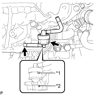
Text in Illustration *1 Protrusion *2 Groove Install the No. 1 gas filter to the gas filter bracket.
Note
Make sure the protrusion of the No. 1 gas filter is aligned with the groove of the gas filter bracket.
-
Connect the vacuum hose.
-
-
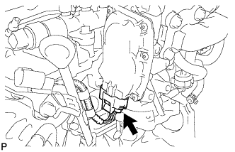
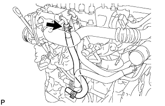
INSTALL DIESEL TURBO PRESSURE SENSOR
-
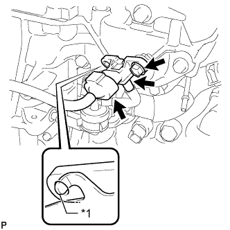
Text in Illustration *1 Protrusion Install the sensor with the bolt.
- Torque:
- 8.8 N*m { 90 kgf*cm, 78 in.*lbf }
Note
Make sure the protrusion of the gas filter bracket is inserted into the hole of the sensor.
-
Connect the sensor connector.
-
Connect the vacuum hose.
-
-
INSTALL ENGINE OIL LEVEL DIPSTICK GUIDE
-
Install a new O-ring to the engine oil level dipstick guide.
-
Install the engine oil level dipstick guide with the 2 bolts.
- Torque:
- 33 N*m { 337 kgf*cm, 24 ft.*lbf }
-
Connect the connector and attach the wire harness clamp to the engine oil level dipstick guide.
-
Install the engine oil level dipstick.
-
-
INSTALL INTAKE MANIFOLD INSULATOR
-
Install the intake manifold insulator to the intake manifold.
-
-
INSTALL COMMON RAIL ASSEMBLY
-
Install the common rail with the 2 bolts.
- Torque:
- 21 N*m { 209 kgf*cm, 15 ft.*lbf }
-
Using pliers, grip the claws of the clip and slide the clip to connect the fuel hose.
-
-
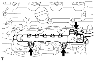
INSTALL INJECTION PIPE SUB-ASSEMBLY
-
Using a 14 mm union nut wrench, tighten the 4 nuts at the common rail end of the injection pipes.
- Torque:
- 30 N*m { 306 kgf*cm, 22 ft.*lbf }
Note
Use the formula to calculate special torque values for situations where a union nut wrench is combined with a torque wrench Click here.
-
Using a 14 mm union nut wrench, tighten the 4 nuts at the injector end of the injection pipes.
- Torque:
- 30 N*m { 306 kgf*cm, 22 ft.*lbf }
Note
Use the formula to calculate special torque values for situations where a union nut wrench is combined with a torque wrench Click here.
-
Install the 4 injection pipe clamps with the 2 bolts.
- Torque:
- 5.0 N*m { 51 kgf*cm, 44 in.*lbf }
-
-
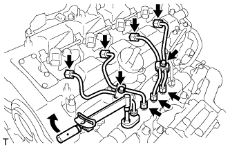
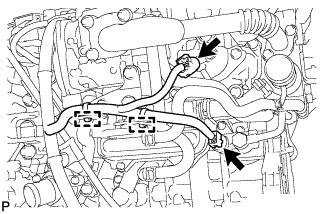
INSTALL FUEL INLET PIPE SUB-ASSEMBLY
-
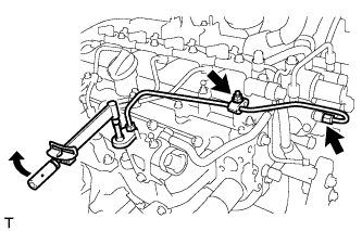
Temporarily install the fuel inlet pipe with the 2 clamps and nut.
-
Using a 14 mm union nut wrench, first tighten the nut at the common rail end of the fuel inlet pipe.
- Torque:
- 30 N*m { 306 kgf*cm, 22 ft.*lbf }
Note
Use the formula to calculate special torque values for situations where a union nut wrench is combined with a torque wrench Click here.
-
Using a 14 mm union nut wrench, tighten the nut at the supply pump end of the fuel inlet pipe.
- Torque:
- 30 N*m { 306 kgf*cm, 22 ft.*lbf }
Note
Use the formula to calculate special torque values for situations where a union nut wrench is combined with a torque wrench Click here.
-
Tighten the No. 2 injection pipe clamp nut.
- Torque:
- 5.0 N*m { 51 kgf*cm, 44 in.*lbf }
-
-
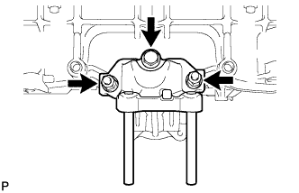
INSTALL ELECTRIC EGR CONTROL VALVE ASSEMBLY
-
Text in Illustration *1 Protrusion Install a new gasket.
Note
Make sure the protrusion of the gasket is facing upward as shown in the illustration.
-
Install the electric EGR control valve.
-
-
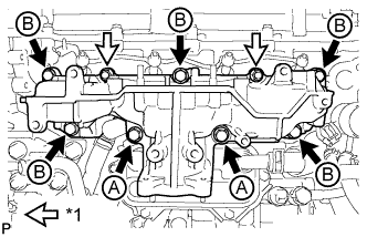
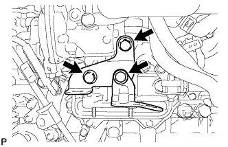
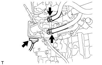
INSTALL NO. 2 EGR PIPE SUB-ASSEMBLY
-
Install a new gasket to the electric EGR control valve.
-
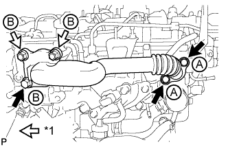
Text in Illustration *1 Nut Temporarily install the No. 2 EGR pipe with the 3 bolts and 2 nuts.
Bolt Length Item Specified Condition Bolt A 25 mm (0.984 in.) Bolt B 70 mm (2.76 in.) -
Tighten the 2 bolts labeled A shown in the illustration.
- Torque:
- 24 N*m { 245 kgf*cm, 18 ft.*lbf }
-
Tighten the bolt and 2 nuts labeled B shown in the illustration.
- Torque:
- 24 N*m { 245 kgf*cm, 18 ft.*lbf }
-
Connect the electric EGR control valve connector.
-
-
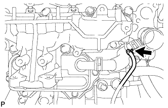
CONNECT NO. 8 WATER BY-PASS HOSE
-
INSTALL NO. 7 WATER BY-PASS HOSE
-
INSTALL EGR VALVE BRACKET
-
Install the 2 EGR valve brackets with the 3 bolts.
- Torque:
- 24 N*m { 245 kgf*cm, 18 ft.*lbf }
-
Connect the 2 connectors and attach the 2 wire harness clamps.
-
-
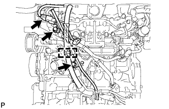
CONNECT ENGINE WIRE
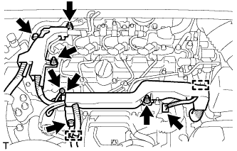
-
Connect the engine wire with the bolt and 3 nuts.
- Torque:
- 8.5 N*m { 87 kgf*cm, 75 in.*lbf }
-
Install the wire harness bracket with the bolt.
- Torque:
- 13 N*m { 133 kgf*cm, 10 ft.*lbf }
-
Attach the 2 wire harness clamps.
-
Connect the glow plug wire harness with the nut and grommet.
- Torque:
- 4.0 N*m { 41 kgf*cm, 35 in.*lbf }
-
Connect the pressure discharge valve connector.
-
Connect the fuel pressure sensor connector.
-
-
INSTALL DIESEL THROTTLE BODY ASSEMBLY
-
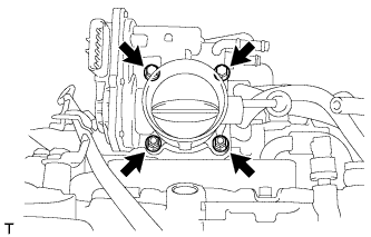
Install a new gasket and the diesel throttle body with the 2 nuts and 2 bolts.
- Torque:
- 11 N*m { 112 kgf*cm, 8 ft.*lbf }
-
Connect the throttle position sensor and throttle motor connector.
-
Connect the No. 6 water by-pass hose to the throttle body.
-
Connect the No. 7 water by-pass hose to the throttle body.
-
-
INSTALL NO. 3 AIR HOSE
Note
Before installation, remove any oil residue from the inside of pipe and hose.
-
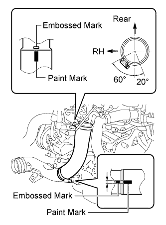
Align the paint mark of the No. 3 air hose with the embossed mark of the throttle body.
-
Align the paint mark of the No. 3 air hose with the embossed mark of the No. 2 air tube.
-
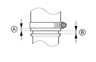
Tighten the clamp of the No. 3 air hose on the diesel throttle body side.
- Torque:
- 6.5 N*m { 66 kgf*cm, 58 in.*lbf }
Tech Tips
-
Align the paint mark of the air hose with the embossed mark and push in the air hose so that distance B is 0 to 2 mm (0 to 0.0787 in.).
-
Position the clamp so that distance A is 4 to 9 mm (0.157 to 0.354 in.).
-
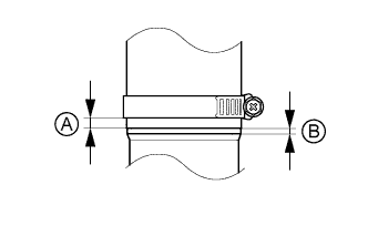
Tighten the clamp of the No. 3 air hose on the No. 2 air tube side.
- Torque:
- 6.5 N*m { 66 kgf*cm, 58 in.*lbf }
Tech Tips
-
Align the paint mark of the air hose with the embossed mark and push in the air hose so that distance B is 0 to 2 mm (0 to 0.0787 in.).
-
Position the clamp so that distance A is 9 to 15 mm (0.354 to 0.591 in.).
-
-
ADD ENGINE OIL
-
Add new engine oil.
Standard Oil Grade Oil Grade Oil Viscosity (SAE) ACEA C2 - 0W-30
- 5W-30
Standard Capacity Item Specified Condition Drain and refill with oil filter change 5.9 liters (6.2 US qts, 5.2 Imp. qts) Drain and refill without oil filter change 5.5 liters (5.8 US qts, 4.8 Imp. qts) Dry fill 6.7 liters (7.1 US qts, 5.9 Imp. qts)
-
-
CONNECT CABLE TO NEGATIVE BATTERY TERMINAL
Note
When disconnecting the cable, some systems need to be initialized after the cable is reconnected Click here.
-
BLEED AIR FROM FUEL SYSTEM
-
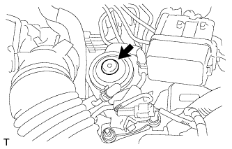
Using the hand pump mounted on the fuel filter cap, bleed the air from the fuel system. Continue pumping until the pump resistance increases.
Note
-
Hand pump pumping speed: Max. 2 strokes/ sec.
-
The hand pump must be pushed with a full stroke during pumping.
-
When the fuel pressure at the supply pump inlet port reaches a saturated pressure, the hand pump resistance increases.
-
If pumping is interrupted during the air bleeding process, fuel in the fuel line may return to the fuel tank. Continue pumping until the hand pump resistance increases.
-
If the hand pump resistance does not increase despite consecutively pumping 200 times or more, there may be a fuel leak between the fuel tank and fuel filter, the hand pump may be malfunctioning, or the vehicle may have run out of fuel.
-
If air bleeding using the hand pump is incomplete, the common rail pressure does not rise to the pressure range necessary for normal use, and the engine cannot be started.
-
-
Start the engine.
Note
-
Even if air bleeding using the hand pump has been completed, the starter may need to be cranked for 10 seconds or more to start the engine.
-
Do not crank the engine continuously for more than 20 seconds. The battery may be discharged.
-
Use a fully-charged battery.
-
When the engine can be started, proceed to the next step.
-
If the engine cannot be started, bleed the air again using the hand pump until the hand pump resistance increases (refer to the procedures above). Then start the engine.
-
-
Turn the ignition switch off.
-
Connect the intelligent tester to the DLC3.
-
Turn the ignition switch to ON and turn the intelligent tester on.
-
Clear the DTCs Click here.
-
Start the engine.*1
-
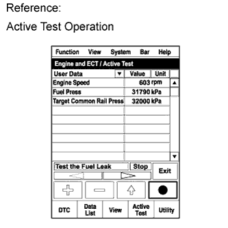
Enter the following menus: Powertrain / Engine and ECT / Active Test / Test the Fuel Leak.*2
-
Perform the following test 5 times with on/off intervals of 10 seconds: Active Test / Test the Fuel Leak.*3
-
Allow the engine to idle for 3 minutes or more after performing the Active Test for the fifth time.
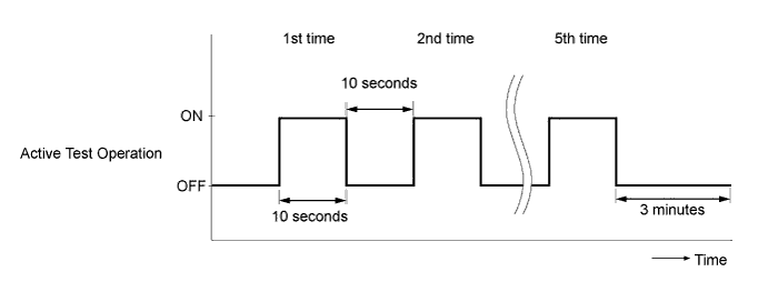
Tech Tips
When the Active Test "Test the Fuel Leak" is used to change the pump control mode, the actual fuel pressure inside the common rail drops below the target fuel pressure when the Active Test is off, but this is normal and does not indicate a pump malfunction.
-
Enter the following menus: Powertrain / Engine and ECT / DTC.
-
Read Current DTCs.
-
When no DTCs are output, the air bleeding is completed.
-
If any DTCs are output, proceed to the next step.
-
-
Clear the DTCs Click here.
-
Repeat steps *1 to *3.
-
Enter the following menus: Powertrain / Engine and ECT / DTC.
-
Read Current DTCs.
OK No DTCs are output.
-
-
ADD ENGINE COOLANT
-
Tighten the radiator drain cock plug by hand.
-
Tighten the cylinder block drain cock plug.
- Torque:
- for Type A
- 13 N*m { 130 kgf*cm, 9 ft.*lbf }
- for Type B
- 25 N*m { 255 kgf*cm, 18 ft.*lbf }
-
Add TOYOTA Super Long Life Coolant (SLLC) to the radiator reservoir filler opening.
Standard Capacity Item Specified Condition w/o Power Heater 7.4 liters (7.8 US qts, 6.5 Imp. qts) w/ Power Heater 7.8 liters (8.2 US qts, 6.9 Imp. qts) Tech Tips
TOYOTA vehicles are filled with TOYOTA SLLC at the factory. In order to avoid damage to the engine cooling system and other technical problems, only use TOYOTA SLLC or similar high quality ethylene glycol based non-silicate, non-amine, non-nitrite, non-borate coolant with long-life hybrid organic acid technology (coolant with long-life hybrid organic acid technology is a combination of low phosphates and organic acids).
Note
Never use water as a substitute for engine coolant.
-
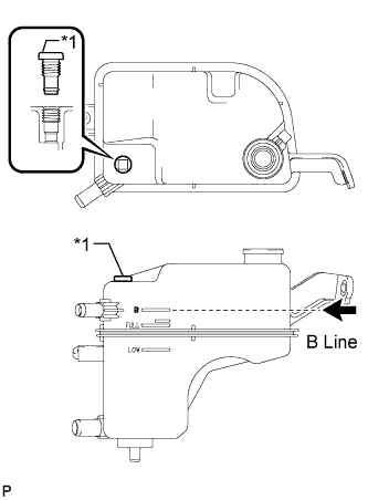
Text in Illustration *1 Air Release Plug Remove the radiator cap and air release plug and add coolant to the B line of the reservoir tank.
-
Squeeze the inlet and outlet radiator hoses several times by hand, and then check the level of the coolant.
If the coolant level is low, add coolant.
-
Install the cap and air release plug, and warm up the engine sufficiently.
- Torque:
- 2.0 N*m { 20 kgf*cm, 18 in.*lbf }
-
Bleed air from the cooling system.
Note
-
Before starting the engine, turn the A/C switch off.
-
Adjust the air conditioning temperature setting to MAX (HOT).
-
Adjust the air conditioning blower setting to Lo.
-
Warm up the engine until the thermostat opens. While the thermostat is open, allow the coolant to circulate for several minutes.
Tech Tips
The thermostat opening timing can be confirmed by squeezing the inlet radiator hose by hand and sensing vibrations when the engine coolant starts to flow inside the hose.
CAUTION:
When squeezing the radiator hoses:
-
Wear protective gloves.
-
Be careful as the radiator hoses are hot.
-
Keep your hands away from the radiator fan.
-
-
After the engine has warmed up, run the engine according to the following pattern for at least 7 minutes: 3000 rpm for 5 seconds, and then idle speed for 45 seconds (repeat this pattern at least 8 times).
-
Squeeze the inlet and outlet radiator hoses several times by hand to bleed air from the system.
CAUTION:
When squeezing the radiator hoses:
-
Wear protective gloves.
-
Be careful as the radiator hoses are hot.
-
Keep your hands away from the radiator fan.
-
-
-
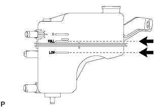
After the engine has cooled down, check that the coolant level is between FULL and LOW.
If the coolant level is low, add coolant until the coolant level reaches the reservoir tank FULL line.
-
-
INSPECT FOR COOLANT LEAK
-
Remove the radiator reservoir cap.
CAUTION:
To avoid the danger of being burned, do not remove the radiator reservoir cap while the engine and radiator are still hot. Thermal expansion will cause hot engine coolant and steam to blow out from the radiator.
-
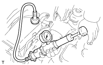
Fill the radiator with coolant, and then attach a radiator cap tester.
-
Warm up the engine.
-
Pump the radiator cap tester to 118 kPa (1.2 kgf/cm2, 17 psi), and then check that the pressure does not drop.
If the pressure drops, check the hoses, radiator and water pump for leakage.
If there are no signs of external coolant leaks, check the heater core, cylinder block and head.
-
Reinstall the radiator reservoir cap.
-
-
INSPECT FOR OIL LEAK
-
Warm up the engine and check for an engine oil leak.
-
-
INSPECT FOR FUEL LEAK
Tech Tips
Using the intelligent tester to perform Active Tests allow relays, VSVs, actuators and other items to be operated without removing any parts. This non-intrusive functional inspection can be very useful because intermittent operation may be discovered before parts or wiring is disturbed. Performing Active Tests early in troubleshooting is one way to save diagnostic time. Data List information can be displayed while performing Active Tests.
-
Perform Active Test.
-
Connect the intelligent tester to the DLC3.
-
Turn the ignition switch to ON.
-
Start the engine.
-
Turn the intelligent tester on.
-
Enter the following menus: Powertrain / Engine / Active Test.
-
Perform the Active Test.
Tester Display Test Part Control Range Diagnostic Notes Test the Fuel Leak Pressurizes common rail internal fuel pressure, and checks for fuel leaks Stop/Start Performs inspection of the high pressure fuel system.
-
Engine Speed: 2050 rpm
-
Fuel Pressure: 172000 kPa
-
Target Common Rail Pressure: 176000 kPa
-
Target Pump SCV Current: 1.4 A
-
MAP: 176 kPa
-
MAF: 39 g/sec.
-
-
-
-
INSPECT ENGINE OIL LEVEL
-
Warm up the engine, stop the engine and wait 5 minutes. The engine oil level should be between the dipstick low level mark and full level mark.
If low, check for leakage and add oil up to the full level mark.
Note
Do not fill engine oil above the full level mark.
-
-
INSTALL ENGINE UNDER COVER
-
Install the engine under cover with the 11 clips.
-
-
INSTALL FRONT LOWER BUMPER ABSORBER
-
Insert the 2 hooks of the front lower bumper absorber into the installation holes on the body to install the front lower bumper absorber.
-
Install 8 bolts and 3 screws.
-
Install the 4 screws and 2 bolts.
-
-
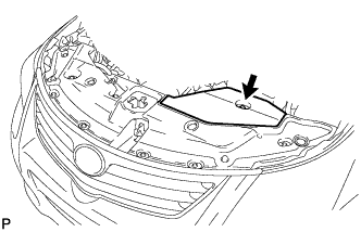
INSTALL RADIATOR SUPPORT OPENING COVER
-
Install the radiator support opening cover with the 8 clips.
-
-
INSTALL ENGINE ROOM SIDE COVER
-
Attach the 4 clips install the engine room side cover.
-
-
INSTALL NO. 1 ENGINE COVER
-
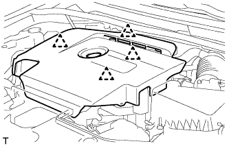
Attach the 4 clips to install the No. 1 engine cover.
-