ДВИГАТЕЛЬ В СБОРЕ УСТАНОВКА

Note
for Manual Transaxle:
When the transaxle is removed, be sure to use a new clutch release with bearing cylinder and new installation bolts. Removal of the transaxle allows the compressed clutch release with bearing cylinder to return to its original position, and dust could damage the seal of the clutch release with bearing cylinder, possibly causing clutch fluid leaks.
-
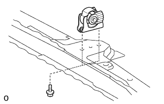
INSTALL ENGINE MOUNTING INSULATOR SUB-ASSEMBLY LH
Tech Tips
Perform this procedure only when replacement of the engine mounting insulator is necessary.
-
Install the engine mounting insulator with the 4 bolts.
- Torque:
- 95 N*m { 969 kgf*cm, 70 ft.*lbf }
-
-
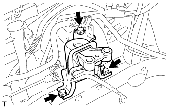
INSTALL ENGINE MOUNTING INSULATOR SUB-ASSEMBLY RH
Tech Tips
Perform this procedure only when replacement of the engine mounting insulator is necessary.
-
Install the engine mounting insulator with the 3 bolts.
- Torque:
- 95 N*m { 969 kgf*cm, 70 ft.*lbf }
-
Install the 2 cooler brackets with the 2 bolts and nut.
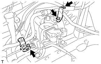
- Torque:
- 9.8 N*m { 100 kgf*cm, 87 in.*lbf }
-
Connect the cooler pipe clamp.
-
-
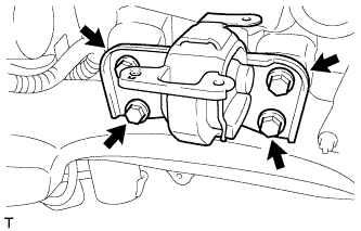
INSTALL REAR ENGINE MOUNTING INSULATOR
Tech Tips
Perform this procedure only when replacement of the engine mounting insulator is necessary.
-
Install the engine mounting insulator with the 2 bolts and 2 nuts.
- Torque:
- 95 N*m { 969 kgf*cm, 70 ft.*lbf }
-
-
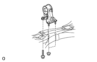
INSTALL FRONT ENGINE MOUNTING INSULATOR
Tech Tips
Perform this procedure only when replacement of the engine mounting insulator is necessary.
-
Install the engine mounting insulator with the 2 bolts.
- Torque:
- 95 N*m { 969 kgf*cm, 70 ft.*lbf }
-
-
INSTALL ENGINE HANGER
-
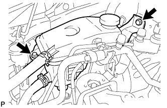
Disconnect the air fuel ratio sensor connector and remove the bolt and air fuel ratio sensor bracket.
-
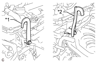
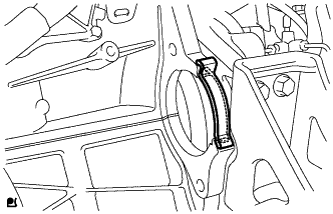
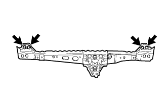
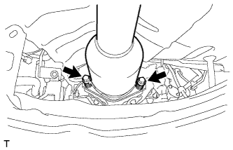
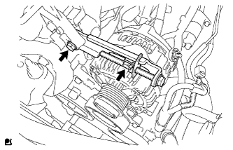
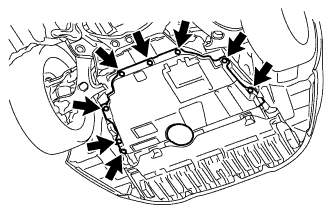
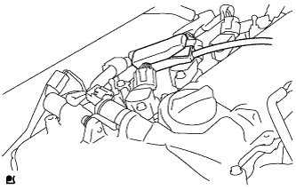
Install the 2 engine hangers with 2 bolts as shown in the illustration.
- Torque:
- 43 N*m { 438 kgf*cm, 32 ft.*lbf }
Text in Illustration *1 No. 1 Engine Hanger *2 No. 2 Engine Hanger Tech Tips
No. 1 Engine Hanger 12281-37021 No. 2 Engine Hanger 12282-37011 Bolt 91552-81050 -
Attach an engine sling device and hang the engine with a chain block.
-
-
REMOVE ENGINE STAND
-
Attach a sling device and hang the engine with a chain block.
-
Lift the engine and remove it from the engine stand.
-
-
INSTALL ENGINE WIRE
-
Install the engine wire to the engine.
-
-
INSTALL CLUTCH RELEASE WITH BEARING CYLINDER ASSEMBLY (for Manual Transaxle)
-
Install the clutch release with bearing cylinder assembly Click here.
-
-
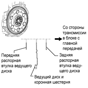
INSTALL DRIVE PLATE AND RING GEAR SUB-ASSEMBLY (for Automatic Transaxle)
-
Using SST, hold the crankshaft.
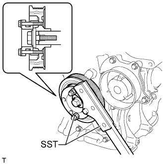
- SST
- 09330-00021
- 09213-58014 ( 91551-80840 )
-
Install the front spacer, drive plate and rear spacer onto the crankshaft.
-
Clean the bolts and bolt holes.
-
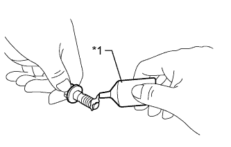
Apply adhesive to 2 or 3 threads at the end of the 8 bolts.
Text in Illustration *1 Adhesive Adhesive Toyota Genuine Adhesive 1324, Three Bond 1324 or equivalent -
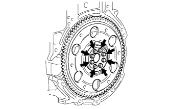
Install the front spacer, drive plate and rear spacer with the 8 bolts. Uniformly tighten the 8 bolts.
- Torque:
- 88 N*m { 897 kgf*cm, 65 ft.*lbf }
-
-
INSTALL FLYWHEEL SUB-ASSEMBLY (for Manual Transaxle)
-
Using SST, hold the crankshaft.
- SST
- 09330-00021
- 09213-58014 ( 91551-80840 )
-
Clean the bolts and bolt holes.
-
Apply adhesive to 2 or 3 threads at the end of 8 bolts.
Text in Illustration *1 Adhesive Adhesive Toyota Genuine Adhesive 1324, Three Bond 1324 or equivalent -
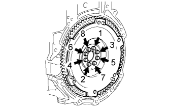
Uniformly install and tighten the 8 bolts in several steps in the sequence shown in the illustration.
- Torque:
- 49 N*m { 500 kgf*cm, 36 ft.*lbf }
-
Mark the top of the bolts with paint.
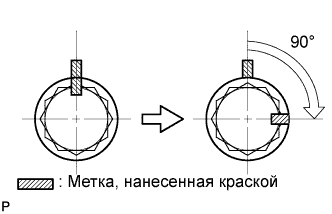
-
Retighten the 8 bolts an additional 90° in the same sequence.
-
Check that the paint marks are now at a 90° angle to the top.
-
-
INSTALL CLUTCH DISC ASSEMBLY (for Manual Transaxle)
-
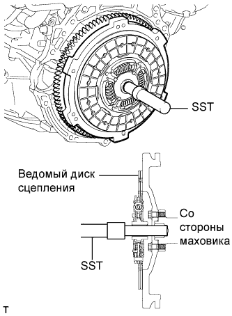
Вставьте SST в ведомый диск сцепления в сборе, а затем закрепите их вместе на маховике в сборе.
- SST
- 09301-00210
Note
Следите за тем, чтобы ведомый диск сцепления был вставлен правильной стороной.
-
-
INSTALL CLUTCH COVER ASSEMBLY (for Manual Transaxle)
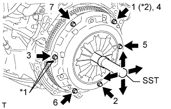
Обозначения на рисунке *1 Метка *2 Устанавливается временно -
Совместите метку на кожухе сцепления в сборе с меткой на маховике в сборе.
-
Затяните 6 болтов в последовательности, показанной на рисунке, начиная с болта, который располагается сверху рядом со штифтом.
- SST
- 09301-00210
- Torque:
- 19 Н*м { 195 кгс*см, 14 фунт-сила-дюймов }
Tech Tips
-
Заворачивайте болты равномерно, по одному, в последовательности, показанной на рисунке.
-
Убедитесь, что ведомый диск сцепления в сборе располагается в центре, после чего затяните болты, слегка смещая SST вверх-вниз и вправо-влево.
-
-
INSPECT AND ADJUST CLUTCH COVER ASSEMBLY (for Manual Transaxle)
-
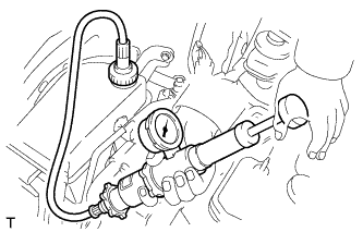
С помощью индикатора часового типа с роликовым датчиком проверьте отклонение конца диафрагменной пружины.
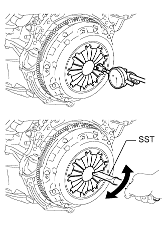
Максимальное отклонение 0,5 мм (0,0196 дюйма) Если отклонение конца диафрагменной пружины превышает максимально допустимое, отрегулируйте его с помощью SST.
- SST
- 09333-00013
-
-
INSTALL AUTOMATIC TRANSAXLE ASSEMBLY (for Automatic Transaxle)
-
Install the automatic transaxle assembly Click here.
-
-
INSTALL MANUAL TRANSAXLE ASSEMBLY (for Manual Transaxle)
-
Install the manual transaxle assembly Click here.
-
-
INSTALL FLYWHEEL HOUSING SIDE COVER
-
Установите боковую крышку картера маховика на блок цилиндров.
-
-
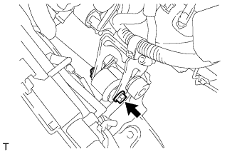
INSTALL STARTER ASSEMBLY
-
Установите стартер и закрепите его 2 болтами.
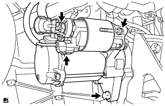
- Torque:
- 37 Н*м { 380 кгс*см, 27 фунт-сила-дюймов }
-
Подсоедините разъем.
-
Подсоедините провод стартера, зафиксировав соединение гайкой.
- Torque:
- 9,8 Н*м { 100 кгс*см, 87 фунт-сила-дюймов }
-
Подсоедините крышку контакта.
-
-
TEMPORARILY INSTALL FRONT SUSPENSION CROSSMEMBER SUB-ASSEMBLY
-
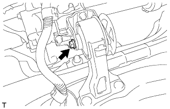
Temporarily install the rear engine mounting insulator to the engine mounting bracket with the through bolt.
-
-
INSTALL ENGINE ASSEMBLY WITH TRANSAXLE
-
Place the engine on an engine lifter.
Tech Tips
Place the engine on wooden blocks or equivalent so that the engine is level.
-
Operate the engine lifter and install the engine to the vehicle.
CAUTION:
Do not raise the engine more than necessary. If the engine is raised excessively, the vehicle may also be lifted up.
Note
-
Make sure that the engine is clear of all wiring and hoses.
-
While raising the engine into the vehicle, do not allow it to contact the vehicle.
-
-
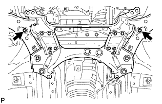
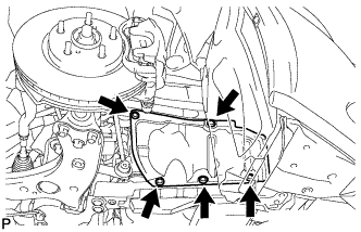
Temporarily install the front suspension crossmember with 2 new bolts.
-
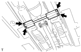
Temporarily install the member brace rear RH and LH with 2 new bolts and the 4 bolts.
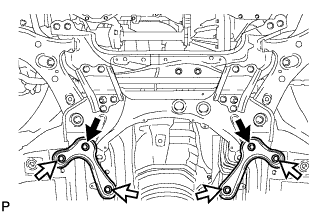
Text in Illustration 
New Bolt 
Bolt -
Install the engine mounting insulator LH with the through bolt and nut.
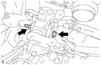
- Torque:
- 56 N*m { 571 kgf*cm, 41 ft.*lbf }
-
Install the engine mounting insulator RH with the bolt and 2 nuts.
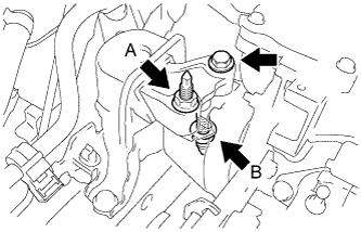
- Torque:
- for bolt and nut A
- 95 N*m { 969 kgf*cm, 70 ft.*lbf }
- for nut B
- 52 N*m { 530 kgf*cm, 38 ft.*lbf }
-
Tighten the 2 front suspension member bolts.
- Torque:
- 137 N*m { 1397 kgf*cm, 101 ft.*lbf }
-
Tighten the 6 member brace rear bolts.
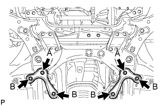
- Torque:
- for bolt A
- 137 N*m { 1397 kgf*cm, 101 ft.*lbf }
- for bolt B
- 93 N*m { 948 kgf*cm, 69 ft.*lbf }
-
Remove the 2 bolts and 2 engine hangers.
-
Install the air fuel ratio sensor bracket with the bolt. Then connect the air fuel ratio sensor connector.
- Torque:
- 60 N*m { 612 kgf*cm, 44 ft.*lbf }
-
-
INSTALL FRONT CROSSMEMBER SUB-ASSEMBLY
-
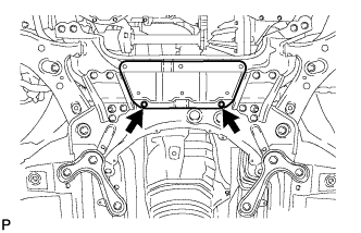
Temporarily install the front crossmember with the 4 bolts.
-
Temporarily install the front engine mounting insulator to the front engine mounting bracket with the bolt and nut.
-
Tighten the 4 front crossmember bolts.
- Torque:
- 96 N*m { 979 kgf*cm, 71 ft.*lbf }
-
Tighten the front engine mounting insulator bolt and nut.
- Torque:
- 145 N*m { 1479 kgf*cm, 107 ft.*lbf }
-
-
TIGHTEN FRONT SUSPENSION CROSSMEMBER SUB-ASSEMBLY
-
Tighten the rear engine mounting insulator bolt.
- Torque:
- 95 N*m { 969 kgf*cm, 70 ft.*lbf }
-
-
INSTALL FRONT SUSPENSION MEMBER REINFORCEMENT LH
-
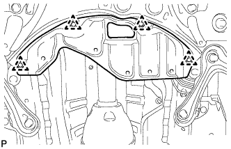
Install the reinforcement with the 4 bolts.
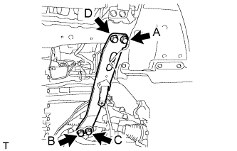
- Torque:
- 96 N*m { 979 kgf*cm, 71 ft.*lbf }
Note
Tighten the bolts in the order of C, B, D and A.
-
-
INSTALL FRONT SUSPENSION MEMBER REINFORCEMENT RH
-
Install the reinforcement with the 4 bolts.
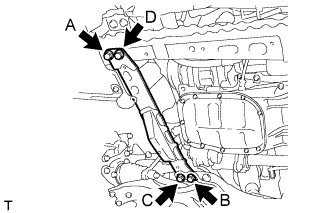
- Torque:
- 96 N*m { 979 kgf*cm, 71 ft.*lbf }
Note
Tighten the bolts in the order of C, B, D and A.
-
-
INSTALL DRIVE PLATE AND TORQUE CONVERTER SETTING BOLT (for Automatic Transaxle)
-
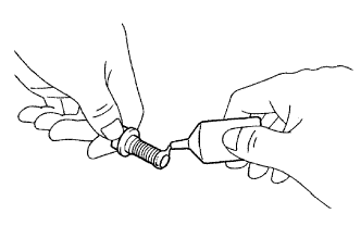
Apply a few drops of adhesive to 2 or 3 threads of the 6 torque converter setting bolts tips.
Adhesive Toyota Genuine Adhesive 1324, Three Bond 1324 or equivalent -
Turn the crankshaft to gain access to the installation locations of the 6 torque converter setting bolts and install each bolt while holding the crankshaft pulley bolt with a wrench.
- Torque:
- 41 N*m { 418 kgf*cm, 30 ft.*lbf }
Note
Install the black bolt first, and then the 5 silver bolts.
-
Install the flywheel housing under cover.
-
-
INSTALL FRONT DRIVE SHAFT ASSEMBLY LH
-
Смажьте шлицевую часть вала внутреннего шарнира маслом.
Tech Tips
Необходимо использовать масло такого же типа, что применяется для трансмиссии.
-
Совместите шлицы валов и вбейте приводной вал с помощью латунного стержня и молотка.
Note
-
Перед установкой приводного вала ведущего колеса убедитесь, что разрез пружинного стопорного кольца обращен вниз.
-
Будьте осторожны, чтобы не повредить сальник, чехол или пыльник.
-
-
-
INSTALL FRONT DRIVE SHAFT ASSEMBLY RH
-
Смажьте шлицевую часть вала внутреннего шарнира трансмиссионным маслом.
-
Совместите шлицы вала и надежно вставьте приводной вал.
-
Вверните 2 болта кронштейна подшипника.
- Torque:
- 64 Н*м { 650 кгс*см, 47 фунт-сила-дюймов }
Note
Будьте осторожны, чтобы не повредить сальник, чехол и пыльник.
-
-
INSTALL FRONT AXLE ASSEMBLY LH
-
Install the front axle assembly LH Click here.
-
-
INSTALL FRONT AXLE ASSEMBLY RH
Tech Tips
Use the same procedures described for the LH side.
-
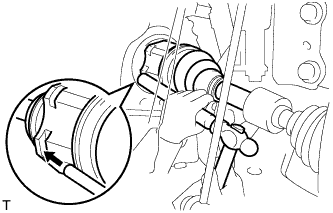
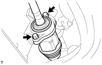
CONNECT FRONT STABILIZER LINK ASSEMBLY LH
-
Подсоедините стойку переднего стабилизатора в сборе к переднему амортизатору с цилиндрической винтовой пружиной, закрепив ее гайкой.
- Torque:
- 74 Н*м { 755 кгс*см, 55 фунт-сила-дюймов }
Tech Tips
Если шаровой шарнир поворачивается вместе с гайкой, зафиксируйте шпильку с помощью шестигранного ключа с головкой 6 мм.
-
-
CONNECT FRONT STABILIZER LINK ASSEMBLY RH
Tech Tips
Use the same procedures described for the LH side.
-
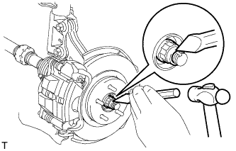
INSTALL FRONT AXLE SHAFT NUT LH
-
Накерните гайку вала передней полуоси с помощью молотка и зубила.
-
-
INSTALL FRONT AXLE SHAFT NUT RH
Tech Tips
Use the same procedures described for the LH side.
-
INSTALL FRONT EXHAUST PIPE ASSEMBLY
-
При помощи штангенциркуля замерьте длину пружины сжатия в свободном состоянии.
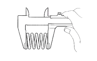
Минимальная длина в свободном состоянии 41,5 мм (1,63 дюйма) Если длина в свободном состоянии меньше минимально допустимой, замените пружину сжатия.
-
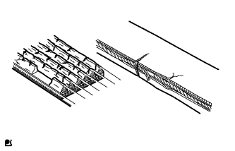
С помощью молотка с пластмассовым покрытием и деревянного бруска запрессуйте новую прокладку до тех пор, пока ее поверхность не окажется на одном уровне с выпускным коллектором.
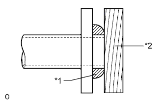
Обозначения на рисунке *1 Прокладка *2 Деревянный брусок Note
-
При установке прокладки соблюдайте ее ориентацию.
-
Повторное использование прокладок запрещено.
-
Действуйте осторожно, чтобы не повредить прокладку.
-
При подсоединении выпускной трубы не надавливайте ей на прокладку.
-
-
Установите 2 опоры выпускной трубы, а затем установите приемную трубу в сборе и закрепите ее 2 болтами и 2 пружинами сжатия.
- Torque:
- 43 Н*м { 438 кгс*см, 32 фунт-сила-дюйма }
-
-
INSTALL FRONT CENTER FLOOR BRACE
-
Установите передний центральный подкос пола и закрепите его 4 болтами.
- Torque:
- 51 Н*м { 520 кгс*см, 38 фунт-сила-дюймов }
-
-
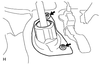
CONNECT NO. 1 STEERING COLUMN HOLE COVER SUB-ASSEMBLY
-
Совместите круглое отверстие в кожухе выходного отверстия рулевой колонки № 1 с выступом тяги рулевого управления и установите кожух.
-
-
CONNECT NO. 2 STEERING INTERMEDIATE SHAFT ASSEMBLY
-
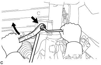
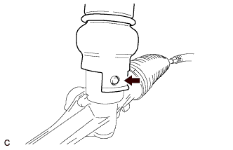
Совместите метки на промежуточном валу № 2 рулевого управления в сборе и промежуточном валу рулевого управления в сборе.
Обозначения на рисунке *1 Метка -
Заверните болт.
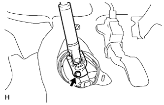
- Torque:
- 35 Н*м { 360 кгс*см, 26 фунт-сила-дюймов }
-
-
INSTALL COLUMN HOLE COVER SILENCER SHEET
-
Установите шумоизолирующую накладку кожуха выходного отверстия рулевой колонки и закрепите ее 2 фиксаторами.
-
Расправьте напольный коврик.
-
-
CONNECT WIRE HARNESS AND HOSE
-
Connect the vacuum hose.
-
Connect the connector tube hose.
-
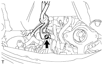
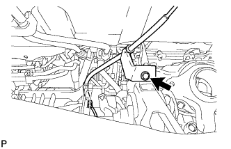
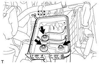
Connect the engine wire with the bolt.
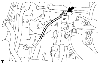
- Torque:
- 29 N*m { 296 kgf*cm, 21 ft.*lbf }
-
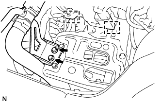
Connect the engine wire with the 2 bolts and clamp.
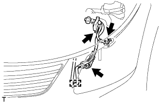
- Torque:
- 8.4 N*m { 86 kgf*cm, 74 in.*lbf }
-
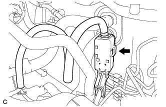
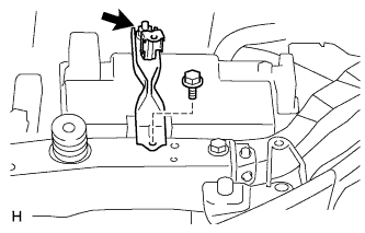
Connect the connector to the battery current sensor.
-
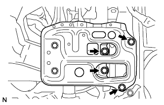
Attach the 2 clamps to install the wire harness, and then install the 2 nuts.
- Torque:
- 8.4 N*m { 86 kgf*cm, 74 in.*lbf }
-
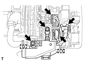
Connect the 3 wire harness connectors to the engine room No. 1 junction block.
-
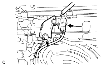
Connect the ECM connector and lower the lever.
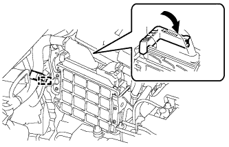
Note
-
When connecting the connector, make sure that dirt, water or other foreign matter does not get caught between the connector and other parts.
-
Make sure that the lever is securely lowered.
-
-
Connect the wire harness clamp.
-
for Automatic Transaxle:
Connect the 2 oil cooler hoses to the oil cooler tube.
-
-
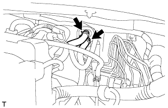
CONNECT HEATER WATER HOSE
-
Connect the 2 heater water hoses.
-
-
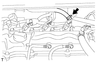
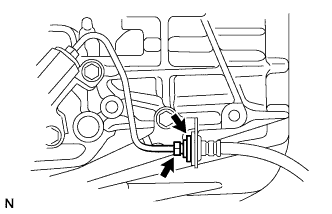
CONNECT FUEL TUBE SUB-ASSEMBLY
-
Connect the fuel tube connector and fuel pipe.
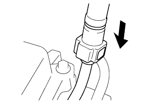
Note
Align the fuel tube connector with the pipe, and then push the fuel tube connector on until the retainer makes a "click" sound. If the connection is tight, apply a small amount of engine oil to the tip of the pipe. After connecting the connector, pull the pipe and connector to make sure that they are securely connected. A206121
-
Attach the claw to install the No. 1 fuel pipe clamp.
-
-
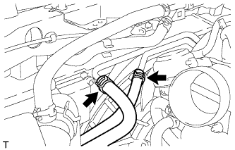
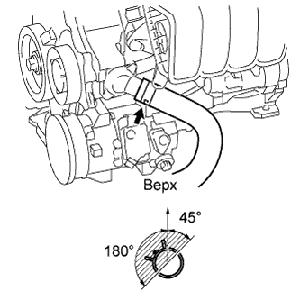
CONNECT NO. 1 RADIATOR HOSE
-
Connect the radiator hose to the cylinder head.
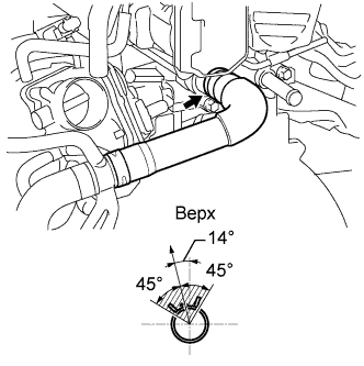
Tech Tips
The direction of the hose clamp is indicated in the illustration.
-
-
CONNECT CLUTCH HOSE (for Manual Transaxle)
-
Connect the clutch hose and install the clip to the clutch hose.
Note
Install the clip as far as it will go.
-
Using a 10 mm union nut wrench, connect the clutch hose to the flexible hose tube while holding the clutch hose.
- Torque:
- 15 N*m { 155 kgf*cm, 11 ft.*lbf }
Note
-
Use the formula to calculate special torque values for situations where a union nut wrench is combined with a torque wrench Click here.
-
Do not kink or damage the clutch hose.
-
Do not allow any foreign matter such as dirt or dust to enter the clutch hose from the clip or bracket.
-
This torque value is effective when the union nut wrench is parallel to the torque wrench.
-
-
CONNECT TRANSMISSION CONTROL CABLE ASSEMBLY (for Manual Transaxle)
-
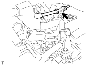
Connect the control cable assembly with the nut.
- Torque:
- 5.0 N*m { 51 kgf*cm, 44 in.*lbf }
-
Connect the 2 transmission control cables with 2 new clips.
-
Install the 2 clips.
-
-
CONNECT TRANSMISSION CONTROL CABLE ASSEMBLY (for Automatic Transaxle)
-
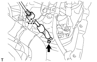
Connect the transmission control cable support together with the cable with the nut.
- Torque:
- 5.0 N*m { 51 kgf*cm, 44 in.*lbf }
-
Connect the transmission control cable to the control cable bracket.
-
Connect the transmission control cable to the bracket with a new clip.
-
Connect the transmission control cable to the control shaft lever with the nut.
- Torque:
- 12 N*m { 122 kgf*cm, 9 ft.*lbf }
-
-
INSTALL BATTERY CARRIER
-
Install the battery carrier with the 4 bolts.
- Torque:
- 19 N*m { 189 kgf*cm, 14 ft.*lbf }
-
Install the radiator pipe with the 2 bolts.
- Torque:
- 19 N*m { 189 kgf*cm, 14 ft.*lbf }
-
Connect the 2 wire harness clamps.
-
-
INSTALL BATTERY TRAY
-
INSTALL BATTERY
-
INSTALL BATTERY CLAMP SUB-ASSEMBLY
-
Install the battery clamp with the bolt and nut.
- Torque:
- for bolt
- 17 N*m { 168 kgf*cm, 12 ft.*lbf }
- for nut
- 3.5 N*m { 36 kgf*cm, 31 in.*lbf }
-
Connect the cable to the positive (+) battery terminal.
- Torque:
- 5.4 N*m { 55 kgf*cm, 48 in.*lbf }
-
-
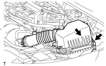
INSTALL AIR CLEANER CASE SUB-ASSEMBLY
-
Install the air cleaner case with the 3 bolts.
- Torque:
- 7.0 N*m { 71 kgf*cm, 62 in.*lbf }
-
Attach the wire harness clamp to the air cleaner case.
-
-
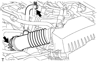
INSTALL AIR CLEANER CAP SUB-ASSEMBLY
-
Подсоедините крышку воздушного фильтра с помощью хомута.
-
Подключите вентиляционный шланг.
-
Подсоедините 2 зажима.
-
Закрепите жгут проводов с помощью 2 зажимов.
-
Подключите разъем датчика массового расхода воздуха.
-
-
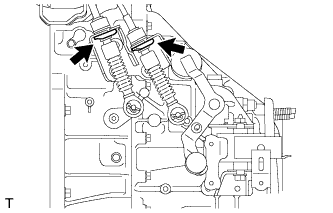
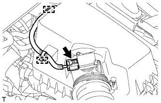
CONNECT COMPRESSOR WITH PULLEY ASSEMBLY
-
Using an E8 "TORX" socket wrench, connect the compressor with pulley assembly with the 2 stud bolts.
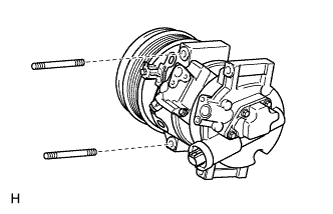
- Torque:
- 9.8 N*m { 100 kgf*cm, 87 in.*lbf }
-
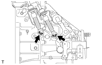
Install the 2 bolts and 2 nuts.
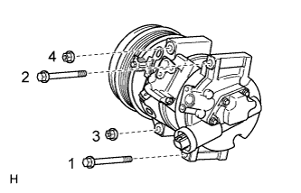
- Torque:
- 25 N*m { 255 kgf*cm, 18 ft.*lbf }
Tech Tips
Tighten the bolts and the nuts in the order shown in the illustration.
-
Connect the connector.
-
-
CONNECT NO. 2 RADIATOR HOSE
-
Connect the radiator hose to the water inlet.
Tech Tips
The direction of the hose clamp is indicated in the illustration.
-
-
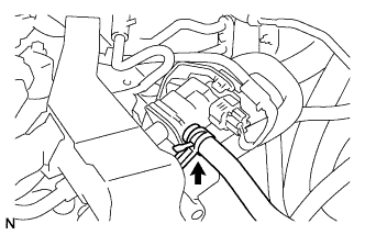
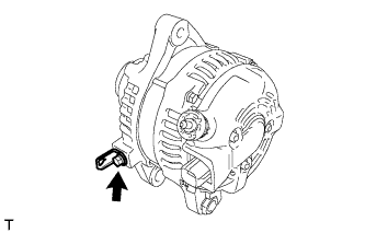
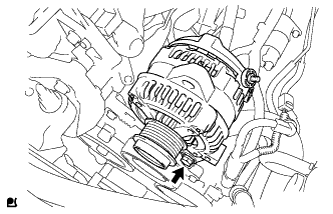
INSTALL GENERATOR ASSEMBLY
-
Установите кронштейн зажима жгута проводов и закрепите его болтом.
- Torque:
- 8,4 Н*м { 85 кгс*см, 74 фунт-сила-дюймов }
-
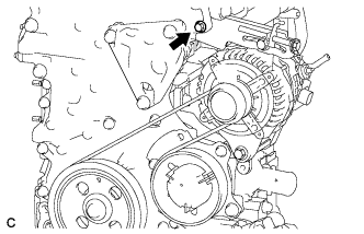
Временно закрепите генератор болтом.
-
Временно закрепите натяжную пластину 2 болтами.
-
Подсоедините жгут проводов к выводу В, закрепите его гайкой и установите крышку вывода.
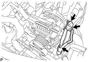
- Torque:
- 9,8 Н*м { 100 кгс*см, 87 фунт-сила-дюймов }
-
Подсоедините разъем и зажим жгута проводов.
-
Установите поликлиновой ремень (см. стр. Click here).
-
Отрегулируйте поликлиновой ремень (см. стр. Click here).
-
Проверьте поликлиновой ремень (см. стр. Click here).
-
Затяните болт.
- Torque:
- 19 Н*м { 189 кгс*см, 14 фунт-сила-дюймов }
-
-
INSTALL V-RIBBED BELT
-
Временно установите поликлиновой ремень.
-
-
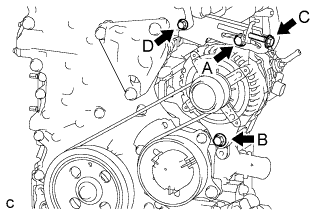
ADJUST V-RIBBED BELT
-
С помощью регулировочного болта C отрегулируйте натяжение поликлинового ремня.
-
Затяните болты А и В.
- Torque:
- Для болта A
- 19 Н*м { 189 кгс*см, 14 фунт-сила-дюймов }
- для болта B
- 43 Н*м { 438 кгс*см, 32 фунт-сила-дюйма }
Note
Не ослабляйте болт D.
-
-
CONNECT RADIATOR RESERVOIR ASSEMBLY
-
Install the grommet to the radiator reservoir.
-
Connect the radiator reservoir with the 2 bolts.
- Torque:
- 5.0 N*m { 51 kgf*cm, 44 in.*lbf }
-
-
CONNECT CABLE TO NEGATIVE BATTERY TERMINAL
Note
When disconnecting the cable, some systems need to be initialized after the cable is reconnected Click here.
-
ADD MANUAL TRANSAXLE OIL (for Manual Transaxle)
-
Добавляйте масло, пока уровень масла не окажется в пределах 5 мм (0,197 дюйма) от нижнего края наливного отверстия трансмиссии.
Масло для механической трансмиссии Фирменное масло для механической трансмиссии LV от компании Toyota или аналогичное Классификация масла API GL-4 и SAE 75W Объем 2,4 литра (2,5 кварты США, 2,1 английской кварты) 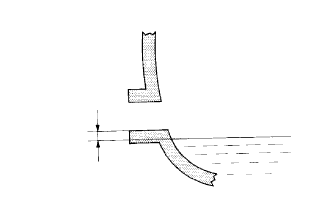
-
Установите на место пробку наливной горловины трансмиссии и новую прокладку.
- Torque:
- 39 Н*м { 400 кгс*см, 29 фунт-сила-дюймов }
Note
-
Перед добавлением масла для трансмиссии убедитесь, что автомобиль находится в горизонтальном положении.
-
Чрезмерно большое или недостаточное количество масла может приводить к возникновению неисправностей.
-
После добавления масла совершите пробную поездку на автомобиле и снова проверьте уровень масла.
-
-
INSPECT MANUAL TRANSAXLE OIL (for Manual Transaxle)
-
Установите автомобиль на ровной поверхности.
-
Кроме автомобилей, предназначенных для эксплуатации на плохих дорогах:
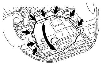
Снимите 8 фиксаторов и отогните защиту картера двигателя.
Tech Tips
Полностью снимать защиту картера двигателя не требуется. Снимите ее частично, чтобы в дальнейшем можно было проверить уровень масла.
-
Для автомобилей, предназначенных для эксплуатации на плохих дорогах:
Снимите передний нижний поглотитель энергии удара (см. стр. Click here).
-
Для автомобилей, предназначенных для эксплуатации на плохих дорогах:
Снимите защиту картера двигателя № 1 (см. стр. Click here).
-
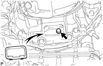
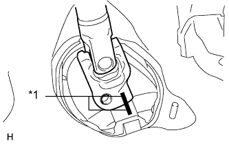
Снимите пробку наливной горловины трансмиссии и прокладку.
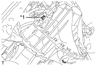
Обозначения на рисунке *1 Пробка наливного отверстия -
Убедитесь в том, что уровень масла попадает в зону 5 мм (0,187 дюйма) от нижнего края наливного отверстия трансмиссии.

Note
Чрезмерно большое или недостаточное количество масла может приводить к возникновению неисправностей.
-
Если уровень масла мал, проверьте, нет ли утечек.
-
Установите на место пробку наливной горловины трансмиссии и новую прокладку.
- Torque:
- 39 Н*м { 400 кгс*см, 29 фунт-сила-дюймов }
-
Для автомобилей, предназначенных для эксплуатации на плохих дорогах:
Установите защиту картера двигателя № 1 (см. стр. Click here).
-
Для автомобилей, предназначенных для эксплуатации на плохих дорогах:
Установите передний нижний поглотитель энергии удара (см. стр. Click here).
-
Кроме автомобилей, предназначенных для эксплуатации на плохих дорогах:
Установите защиту картера двигателя и закрепите ее 8 фиксаторами.
-
-
ADD AUTOMATIC TRANSAXLE FLUID (for Automatic Transaxle)
Fluid type Toyota Genuine ATF WS -
INSPECT AUTOMATIC TRANSAXLE FLUID LEVEL (for Automatic Transaxle)
-
Inspect automatic transaxle fluid level Click here.
-
-
ADD ENGINE COOLANT
-
Tighten the radiator drain cock plug.
-
Add TOYOTA Super Long Life Coolant (SLLC) through the radiator reservoir filler opening until the coolant reaches the B line.
Standard Capacity Item Specified Condition for Manual Transaxle 6.3 liters (6.7 US qts, 5.5 Imp. qts) for Automatic Transaxle 6.2 liters (6.6 US qts, 5.4 Imp. qts) Tech Tips
TOYOTA vehicles are filled with TOYOTA SLLC at the factory. In order to avoid damage to the engine cooling system and other technical problems, only use TOYOTA SLLC or similar high quality ethylene glycol based non-silicate, non-amine, non-nitrite, non-borate coolant with long-life hybrid organic acid technology (coolant with long-life hybrid organic acid technology is a combination of low phosphates and organic acids).
Note
Never use water as a substitute for engine coolant.
-
Squeeze the inlet and outlet radiator hoses several times by hand, and then check the level of the coolant.
If the coolant level is low, add coolant.
-
Install the cap and warm up the engine sufficiently.
-
Bleed air from the cooling system.
Note
-
Before starting the engine, turn the A/C switch off.
-
Adjust the air conditioning temperature setting to MAX (HOT).
-
Adjust the air conditioning blower setting to Lo.
-
Warm up the engine until the thermostat opens. While the thermostat is open, allow the coolant to circulate for several minutes.
Tech Tips
The thermostat opening timing can be confirmed by squeezing the inlet radiator hose by hand, and sensing vibrations when the engine coolant starts to flow inside the hose.
CAUTION:
When squeezing the radiator hose:-
Wear protective gloves.
-
Be careful as the radiator hoses are hot.
-
Keep your hands away from the radiator fan.
-
-
After the engine has warmed up, repeat the following procedure for at least 7 minutes: run the engine at 3000 rpm for 5 seconds, and then at idle speed for 45 seconds (repeat this procedure at least 8 times).
-
Squeeze the inlet and outlet radiator hoses several times by hand to bleed air from the system.
CAUTION:
When squeezing the radiator hose:-
Wear protective gloves.
-
Be careful as the radiator hoses are hot.
-
Keep your hands away from the radiator fan.
-
-
-
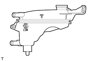
After the engine has cooled down, check that the coolant level is between FULL and LOW lines.
If the coolant level is low, add coolant to the FULL line on the reservoir.
-
-
ADD ENGINE OIL
-
Clean and install the oil pan drain plug together with a new gasket.
- Torque:
- 37 N*m { 377 kgf*cm, 27 ft.*lbf }
-
Add new engine oil.
Standard Oil Grade Oil Grade Oil Viscosity (SAE) API grade SL or SM multigrade engine oil -
15W-40
-
20W-50
API grade SL "Energy-Conserving", SM "Energy-Conserving" or ILSAC multigrade engine oil -
0W-20
-
5W-20
-
5W-30
-
10W-30
Standard Capacity Item Specified Condition Drain and refill without oil filter change 3.9 liters (4.1 US qts, 3.4 Imp. qts) Drain and refill with oil filter change 4.2 liters (4.4 US qts, 3.7 Imp. qts) Dry fill 4.7 liters (5.0 US qts, 4.1 Imp. qts) -
-
Install the oil filler cap.
-
-
INSPECT FOR FUEL LEAK
-
Make sure that there are no fuel leaks after performing maintenance on the fuel system.
-
Connect the intelligent tester to the DLC3.
-
Turn the ignition switch to ON, and push the intelligent tester main switch on.
Note
Do not start the engine.
-
Enter the following menus: Powertrain / Engine and ECT / Active Test / Control the Fuel Pump / Speed.
-
Check that there are no leaks from the fuel system.
-
Turn the ignition switch off.
-
Disconnect the intelligent tester from the DLC3.
-
-
-
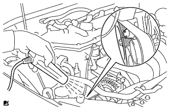
INSPECT FOR COOLANT LEAK
CAUTION:
Во избежание ожогов не снимайте крышку расширительного бачка радиатора, пока двигатель и радиатор не остынут. Тепловое расширение может вызвать выброс из радиатора горячей охлаждающей жидкости и пара.
-
Заполните радиатор охлаждающей жидкостью, а затем подсоедините приспособление для опрессовки системы охлаждения и проверки пробки радиатора.
-
Прогрейте двигатель.
-
С помощью приспособления для опрессовки системы охлаждения и проверки пробки радиатора увеличьте давление в радиаторе до 118 кПа (1,2 кгс/см2, 17 фунтов на кв. дюйм) и убедитесь, что давление не падает.
Если давление снижается, проверьте на наличие утечек шланги, радиатор и насос системы охлаждения. Если нет следов или признаков утечки внешней охлаждающей жидкости, проверьте сердцевину отопителя, блок цилиндров и головку блока цилиндров.
-
-
INSPECT FOR OIL LEAK
-
Start the engine. Make sure that there are no oil leaks from the areas that were worked on.
-
-
INSPECT FOR EXHAUST GAS LEAK
При наличии утечки газа затяните соединения в местах утечки. При необходимости замените поврежденные детали.
-
INSPECT V-RIBBED BELT
-
Убедитесь в отсутствии износа, трещин и других признаков повреждения.
При обнаружении каких-либо дефектов замените поликлиновой ремень.
-
Ремень имеет трещины.
-
Ремень изношен до такой степени, что обнажились волокна
-
Отсутствуют элементы ребер ремня.
-
-
Убедитесь в том, что приводной ремень правильно располагается в углублениях шкива.

Tech Tips
Рукой проверьте, не выскользнул ли ремень из канавок в нижней части шкива. Если ремень выскользнул из канавки шкива, замените ремень. Правильно установите новый поликлиновой ремень.
-
Проверьте прогиб и натяжение поликлинового ремня.
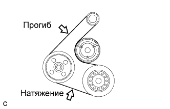
Стандартное отклонение Параметр / Устройство Заданные условия Новый ремень 7,0-8,2 мм (0,276-0,323 дюйма) Ремень, бывший в употреблении 7,6-10,0 мм (0,299-0,394 дюйма) Стандартное натяжение Параметр / Устройство Заданные условия Новый ремень 700-800 Н (70-80 кгс, 157,4-179,8 фунт-силы) Ремень, бывший в употреблении 550-750 Н (55-75 кгс, 123,6-168,6 фунт-силы) Tech Tips
-
При проверке прогиба поликлинового ремня приложите к нему усилие натяжения 98 Н (10 кгс, 22,0 фунт-силы).
-
Проверьте прогиб поликлинового ремня в указанной точке.
-
Натяжение и прогиб поликлинового ремня следует проверять после проворачивания двигателя на 2 оборота.
-
Измерьте натяжение ремня при холодном двигателе.
-
При регулировке ремня установите его натяжение как можно ближе к среднему значению заданного диапазона.
-
При замене ремня новым обязательно выполните следующую процедуру после его регулировки: дайте двигателю поработать 5 мин на холостом ходу, а затем отрегулируйте ремень в соответствии с заданным значением для нового ремня после того, как двигатель остынет.
-
При проверке ремня, использовавшегося более 5 минут, необходимо использовать данные для "ремней, бывших в употреблении".
-
При использовании прибора для проверки натяжения ремня, необходимо сначала проверить его точность по эталонному прибору.
-
-
-
INSPECT IGNITION TIMING
-
Warm up and stop the engine.
-
When using an intelligent tester:
-
Connect the intelligent tester to the DLC3.
-
Start the engine and idle it.
-
Turn the intelligent tester main switch on.
-
Enter the following menus: Powertrain / Engine and ECT / Data List / IGN Advance.
Standard ignition timing 8 to 12° BTDC @ idle Tech Tips
Refer to the intelligent tester operator's manual for further details.
Note
-
Turn all the electrical systems and the A/C off.
-
Check the ignition timing with the cooling fan off.
-
When checking the ignition timing, the shift lever should be in neutral or P (for Automatic Transaxle).
-
-
-
When not using the intelligent tester:
-
Remove the No. 2 cylinder head cover.
-
Connect the tester probe of a timing light to the wire of the ignition coil connector for the No. 1 cylinder.
Note
Use a timing light that detects primary signals.
-
Start the engine and idle it.
-
Using SST, connect terminals 13 (TC) and 4 (CG) of the DLC3.
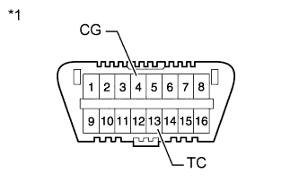
Text in Illustration *1 Front view of DLC3 - SST
- 09843-18040
Note
-
Confirm the terminal numbers before connecting them. Connecting the wrong terminals can damage the engine.
-
When checking the ignition timing, the shift lever should be in neutral or P (for Automatic Transaxle).
-
Using the timing light, check the ignition timing.
Standard ignition timing 8 to 12° BTDC @ idle Note
-
Turn all the electrical systems and the A/C off.
-
Check the ignition timing with the cooling fan off.
-
When checking the ignition timing, the shift lever should be in neutral or P (for Automatic Transaxle).
-
-
Remove SST from the DLC3.
-
Check that the ignition timing advances immediately when the engine speed is increased.
-
Turn the ignition switch off.
-
Remove the timing light.
-
Install the No. 2 cylinder head cover.
-
-
-
INSPECT ENGINE IDLE SPEED
-
Warm up and stop the engine.
-
When using the intelligent tester:
-
Connect the intelligent tester to the DLC3.
-
Turn the ignition switch to ON.
-
Enter the following menus: Powertrain / Engine and ECT / Data List / Engine Speed.
Standard Idle Speed Item Specified Condition for Manual Transaxle 625 to 725 rpm for Automatic Transaxle 625 to 725 rpm Tech Tips
Refer to the intelligent tester operator's manual for further details.
Note
-
Turn all the electrical systems and the A/C off.
-
Check the ignition timing with the cooling fan off.
-
When checking the idling speed, the shift lever should be in neutral or P (for Automatic Transaxle).
-
-
-
Turn the ignition switch off.
-
Disconnect the intelligent tester from the DLC3.
-
When not using the intelligent tester:
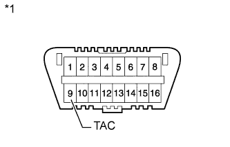
Text in Illustration *1 Front view of DLC3 -
Using SST, connect a tachometer probe to terminal 9 (TAC) of the DLC3.
- SST
- 09843-18030
Note
-
Confirm the terminal numbers before connecting them. Connecting the wrong terminals can damage the engine.
-
When checking the idling speed, the shift lever should be in neutral or P (for Automatic Transaxle).
-
Check the idle speed.
Standard Idle Speed Item Specified Condition for Manual Transaxle 625 to 725 rpm for Automatic Transaxle 625 to 725 rpm -
Disconnect the tachometer probe from the DLC3.
-
-
-
INSPECT CO/HC
-
Start the engine.
-
Run the engine at 2500 rpm for approximately 180 seconds.
-
Insert the CO/HC meter testing probe at least 40 cm (1.31 ft.) into the tailpipe while idling.
-
Check the CO/HC concentration during idling and when the engine is running at 2500 rpm.
Tech Tips
When doing the 2 mode (with the engine idling/ running at 2500 rpm) test, the measuring procedures are determined by applicable local regulations.
If the CO/HC concentration does not comply with the regulations, troubleshoot in the order given below.
-
Check the air fuel ratio sensor Click here and heated oxygen sensor operation Click here.
-
See the table below for possible causes, and then inspect the applicable parts and repair them if necessary.
CO HC Problems Possible Causes Normal High Rough idling -
Faulty ignition:
-
Incorrect timing
-
Plugs are contaminated or shorted, or gaps are defective
-
Incorrect valve clearance
-
Leakage from intake or exhaust valves
-
Leakage from cylinders
Low High Rough idling
(Fluctuating HC reading)
-
Vacuum leaks:
-
PCV hoses
-
Intake manifold
-
Throttle body
-
Brake booster line
-
Lean mixture causing misfire
High High Rough idling
(Black smoke from exhaust)
-
Restricted air cleaner filter element
-
Plugged PCV valve
-
Faulty SFI system:
-
Faulty pressure regulator
-
Faulty engine coolant temperature sensor
-
Faulty mass air flow meter
-
Faulty ECM
-
Faulty injectors
-
Faulty throttle body
-
-
-
-
INSTALL FRONT WHEEL
- Torque:
- 103 N*m { 1050 kgf*cm, 76 ft.*lbf }
-
ADJUST FRONT WHEEL ALIGNMENT
-
Adjust the front wheel alignment Click here.
-
-
PERFORM CLUTCH ENGAGEMENT POINT LEARNING (for Manual Transaxle)
-
INSTALL NO. 2 ENGINE UNDER COVER
-
Install the under cover with the 4 clips.
-
-
INSTALL CENTER NO. 4 ENGINE UNDER COVER
-
Install the under cover with the 2 clips.
-
-
INSTALL REAR ENGINE UNDER COVER RH
-
Закрепите правую защиту картера 5 фиксаторами.
-
-
INSTALL REAR ENGINE UNDER COVER LH
-
Install the under cover LH with the 5 clips.
-
-
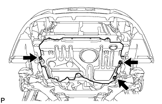
INSTALL NO. 1 ENGINE UNDER COVER (for Rough Road Area Specification Vehicles)
-
Install the under cover with the 3 clips.
-
-
INSTALL NO. 1 ENGINE UNDER COVER
-
Install the under cover with the 10 clips.
-
-
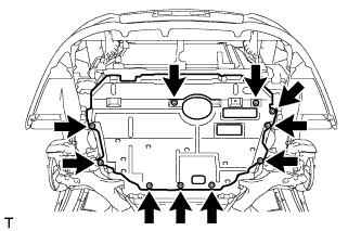
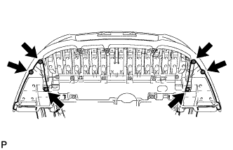
INSTALL FRONT LOWER BUMPER ABSORBER
-
Install the front lower bumper absorber with the 3 screws and 8 bolts.
-
Install the 4 screws and 2 bolts.
-
-
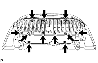
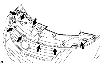
INSTALL RADIATOR SUPPORT OPENING COVER
-
Install the radiator support opening cover with the 8 clips.
-
-
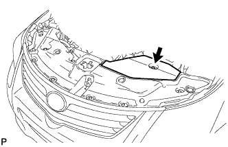
INSTALL ENGINE ROOM SIDE COVER
-
Install the engine room side cover with the clip.
-
-
INSTALL NO. 2 CYLINDER HEAD COVER
-
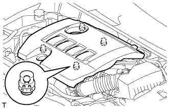
Установите крышку и введите в зацепление 4 фиксатора.
Note
-
Проверьте надежность зацепления фиксаторов.
-
Во время зацепления фиксаторов на крышке не прикладывайте чрезмерных усилий и не допускайте ударов. Это может привести к поломке крышки.
-
-