ЗАДНИЙ САЛЬНИК КОЛЕНЧАТОГО ВАЛА УСТАНОВКА

Note
for Manual Transaxle:
When the transaxle is removed, be sure to use a new clutch release with bearing cylinder and new installation bolts. Removal of the transaxle allows the compressed clutch release with bearing cylinder to return to its original position, and dust could damage the seal of the clutch release with bearing cylinder, possibly causing clutch fluid leaks.
-
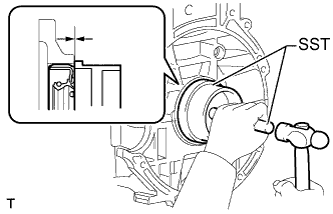
INSTALL ENGINE REAR OIL SEAL
-
Apply MP grease to the lip of a new oil seal.
Note
-
Do not allow foreign matter to contact the lip of the oil seal.
-
Do not allow MP grease to contact the dust seal.
-
-
Using SST and a hammer, tap in the oil seal until its surface is flush with the edges of the cylinder block and crankcase.
- SST
- 09223-15030
- 09950-70010 ( 09951-07100 )
Note
-
Wipe off any extra grease from the crankshaft.
-
Do not tap in the oil seal at an angle.
-
-
INSTALL DRIVE PLATE AND RING GEAR SUB-ASSEMBLY (for Automatic Transaxle)
-
Using SST, hold the crankshaft.
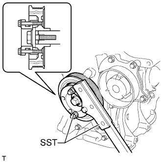
- SST
- 09330-00021
- 09213-58014 ( 91551-80840 )
-
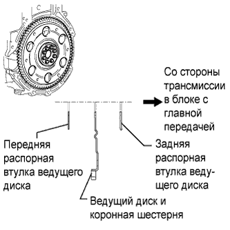
Install the front spacer, drive plate and rear spacer onto the crankshaft.
-
Clean the bolts and bolt holes.
-
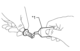
Apply adhesive to 2 or 3 threads at the end of the 8 bolts.
Text in Illustration *1 Adhesive Adhesive Toyota Genuine Adhesive 1324, Three Bond 1324 or equivalent -
Install the front spacer, drive plate and rear spacer with the 8 bolts. Uniformly tighten the 8 bolts.
- Torque:
- 88 N*m { 897 kgf*cm, 65 ft.*lbf }
-
-
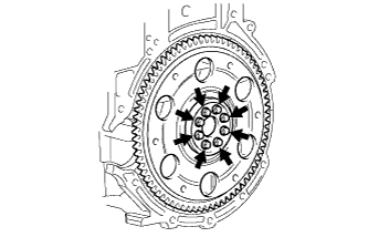
INSTALL FLYWHEEL SUB-ASSEMBLY (for Manual Transaxle)
-
Using SST, hold the crankshaft.
- SST
- 09330-00021
- 09213-58014 ( 91551-80840 )
-
Clean the bolts and bolt holes.
-
Apply adhesive to 2 or 3 threads at the end of 8 bolts.
Text in Illustration *1 Adhesive Adhesive Toyota Genuine Adhesive 1324, Three Bond 1324 or equivalent -
Uniformly install and tighten the 8 bolts in several steps in the sequence shown in the illustration.
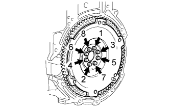
- Torque:
- 49 N*m { 500 kgf*cm, 36 ft.*lbf }
-
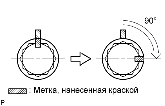
Mark the top of the bolts with paint.
-
Retighten the 8 bolts an additional 90° in the same sequence.
-
Check that the paint marks are now at a 90° angle to the top.
-
-
INSTALL CLUTCH RELEASE WITH BEARING CYLINDER ASSEMBLY (for Manual Transaxle)
-
Install the clutch release with bearing cylinder assembly Click here.
-
-
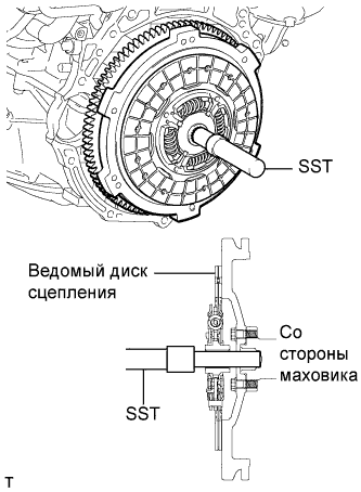
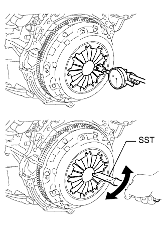
INSTALL CLUTCH DISC ASSEMBLY (for Manual Transaxle)
-
Вставьте SST в ведомый диск сцепления в сборе, а затем закрепите их вместе на маховике в сборе.
- SST
- 09301-00210
Note
Следите за тем, чтобы ведомый диск сцепления был вставлен правильной стороной.
-
-
INSTALL CLUTCH COVER ASSEMBLY (for Manual Transaxle)
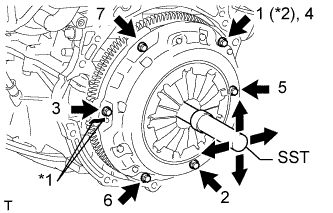
Обозначения на рисунке *1 Метка *2 Устанавливается временно -
Совместите метку на кожухе сцепления в сборе с меткой на маховике в сборе.
-
Затяните 6 болтов в последовательности, показанной на рисунке, начиная с болта, который располагается сверху рядом со штифтом.
- SST
- 09301-00210
- Torque:
- 19 Н*м { 195 кгс*см, 14 фунт-сила-дюймов }
Tech Tips
-
Заворачивайте болты равномерно, по одному, в последовательности, показанной на рисунке.
-
Убедитесь, что ведомый диск сцепления в сборе располагается в центре, после чего затяните болты, слегка смещая SST вверх-вниз и вправо-влево.
-
-
INSPECT AND ADJUST CLUTCH COVER ASSEMBLY (for Manual Transaxle)
-
С помощью индикатора часового типа с роликовым датчиком проверьте отклонение конца диафрагменной пружины.
Максимальное отклонение 0,5 мм (0,0196 дюйма) Если отклонение конца диафрагменной пружины превышает максимально допустимое, отрегулируйте его с помощью SST.
- SST
- 09333-00013
-
-
INSTALL MANUAL TRANSAXLE ASSEMBLY (for Manual Transaxle)
-
Install the manual transaxle assembly Click here.
-
-
INSTALL AUTOMATIC TRANSAXLE ASSEMBLY (for Automatic Transaxle)
-
Install the automatic transaxle assembly Click here.
-
-
INSTALL ENGINE ASSEMBLY WITH TRANSAXLE
-
Install the engine assembly with transaxle Click here.
-