AUTOMATIC TRANSMISSION ASSEMBLY(for 8AR-FTS) REMOVAL
CAUTION / NOTICE / HINT
CAUTION:
The engine assembly with automatic transmission assembly is very heavy. Be sure to follow the procedure described in the repair manual, or the engine lifter may suddenly drop.
PROCEDURE
-
REMOVE ENGINE ASSEMBLY WITH TRANSMISSION
-
REMOVE REAR ENGINE MOUNTING MEMBER
-
REMOVE REAR NO. 1 ENGINE MOUNTING INSULATOR
-
REMOVE NO. 1 EXHAUST MANIFOLD HEAT INSULATOR
-
REMOVE NO. 4 EXHAUST MANIFOLD HEAT INSULATOR
-
REMOVE TURBOCHARGER STAY
-
REMOVE EXHAUST MANIFOLD CONVERTER SUB-ASSEMBLY (TWC: Front and Rear Catalyst)
-
REMOVE TRANSMISSION INSULATOR
-
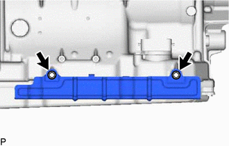
Remove the 2 bolts and transmission insulator from the automatic transmission assembly.
-
-
REMOVE FLOOR SHIFT GEAR SHIFTING ROD SUB-ASSEMBLY
-
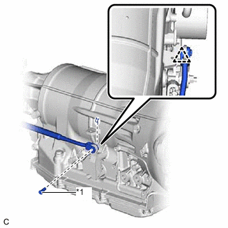
*1 Pin Remove the clip, pin and floor shift gear shifting rod sub-assembly from the transmission control shaft lever RH.
-
-
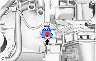
DISCONNECT WIRE HARNESS
-
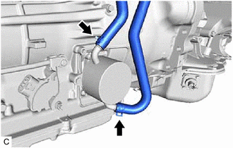
Disconnect the park/neutral position switch assembly connector.
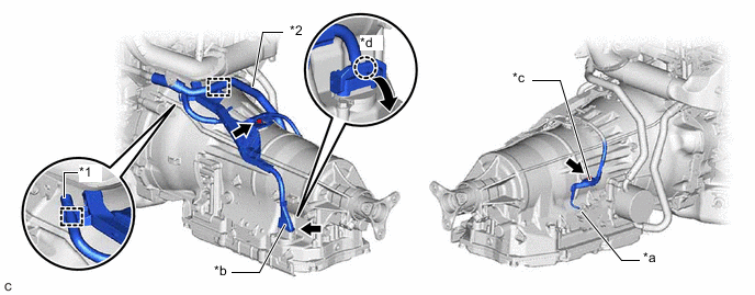
*1 Breather Plug Hose *2 No. 13 Water By-pass Hose *a Park/Neutral Position Switch Assembly Connector *b Transmission Wire Connector *c Nut *d Claw -
Disconnect the transmission wire connector.
Tech Tips
Disengage the claw, pull down the lever, and then disconnect the transmission wire connector.
-
Disengage the clamp to disconnect the breather plug hose from the wire harness.
-
Disengage the clamp to disconnect the No. 13 water by-pass hose from the wire harness.
-
Remove the bolt and nut, and disconnect the wire harness from the automatic transmission assembly.
-
-
REMOVE WIRE HARNESS CLAMP BRACKET
-
Disengage the clamp to disconnect the wire harness.
-
Remove the bolt and wire harness clamp bracket from the automatic transmission assembly.
-
-
DISCONNECT WATER BY-PASS HOSE
-
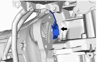
Slide the 2 clips and disconnect the 2 water by-pass hoses from the transmission oil cooler.
-
-
REMOVE NO. 1 AIR TUBE
-
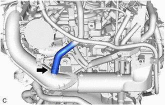
Slide the clip and disconnect the No. 3 ventilation hose from the No. 1 air tube.
-
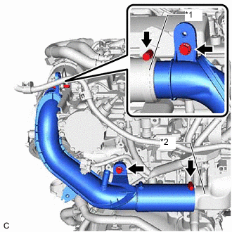
*1 No. 1 Air Hose *2 Intercooler Assembly Remove the 2 bolts and separate the No. 1 air tube from the engine assembly.
-
Loosen the hose clamp and disconnect the No. 1 air tube from the No. 1 air hose.
-
Loosen the hose clamp and remove the No. 1 air tube from the intercooler assembly.
-
-
REMOVE STARTER ASSEMBLY
-
w/o Stop and Start System:
-
w/ Stop and Start System:
-
-
REMOVE FLYWHEEL SIDE COVER
-
Remove the flywheel side cover from the engine assembly.
-
-
REMOVE DRIVE PLATE AND TORQUE CONVERTER ASSEMBLY SETTING BOLT
-
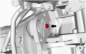
Turn the crankshaft to gain access to the 6 drive plate and torque converter assembly setting bolts and remove each drive plate and torque converter assembly setting bolt while holding the crankshaft pulley bolt with a wrench.
Tech Tips
There will be one black colored drive plate and torque converter assembly setting bolt.
-
-
REMOVE AUTOMATIC TRANSMISSION ASSEMBLY
-
Using a rope or equivalent, support the automatic transmission assembly at the positions shown in the illustration.
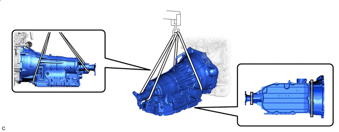

Support Position - - CAUTION:
-
Do not raise the automatic transmission assembly more than necessary.
-
Make sure to confirm the center of gravity of the automatic transmission assembly when supporting it.
-
-
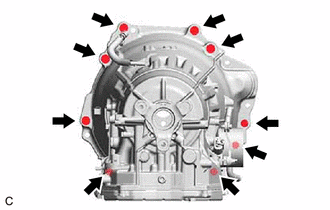
Remove the 9 bolts and automatic transmission assembly from the engine assembly.
Note
To prevent damage to the knock pins, do not pry between the automatic transmission assembly and engine assembly.
-
-
REMOVE TORQUE CONVERTER ASSEMBLY
-
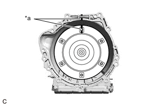
*a Matchmark Put matchmarks on the automatic transmission case sub-assembly and the torque converter assembly.
-
Remove the torque converter assembly from the automatic transmission assembly.
-
-
INSPECT TORQUE CONVERTER ASSEMBLY