INTAKE MANIFOLD REMOVAL
PROCEDURE
-
REMOVE THROTTLE BODY WITH MOTOR ASSEMBLY
-
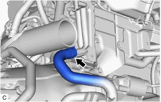
DISCONNECT NO. 2 TURBO WATER HOSE
-
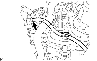
DISCONNECT NO. 1 VACUUM TRANSMITTING HOSE
-
DISCONNECT NO. 8 WATER BY-PASS HOSE
-
DISCONNECT NO. 9 WATER BY-PASS HOSE
-
SEPARATE HEATER WATER PUMP ASSEMBLY
-
DISCONNECT ENGINE WIRE
-
DISCONNECT NO. 1 AIR TUBE
-
DISCONNECT INTERCOOLER ASSEMBLY
-
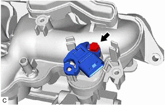
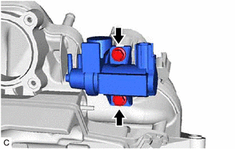
REMOVE PURGE VALVE (PURGE VSV)
-
w/ Canister Pump Module:
-
w/o Canister Pump Module:
-
-
REMOVE INTERCOOLER RESERVE TANK ASSEMBLY
-
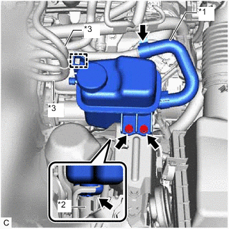
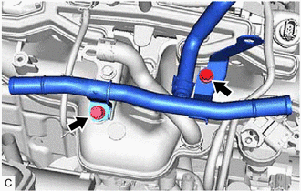
*1 No. 3 Intercooler Cooling Water Hose *2 No. 4 Intercooler Cooling Water Hose *3 Fuel Tube Sub-assembly Disengage the 2 fuel tube sub-assemblies from the intercooler reserve tank assembly.
-
Slide the clip and disconnect the No. 3 intercooler cooling water hose from the No. 2 water by-pass pipe.
-
Remove the 2 bolts and intercooler reserve tank assembly from the intercooler reserve tank bracket.
-
Slide the clip and disconnect the No. 4 intercooler cooling water hose from the intercooler reserve tank assembly.
-
-
REMOVE NO. 1 ENGINE COVER SUB-ASSEMBLY
-
REMOVE AIR CLEANER HOSE ASSEMBLY
-
REMOVE FUEL HOSE BRACKET
-
Disengage the clamp.
-
Disengage the 2 fuel tube sub-assemblies from the fuel hose bracket.
-
Remove the bolt and fuel hose bracket from the intake manifold.
-
-
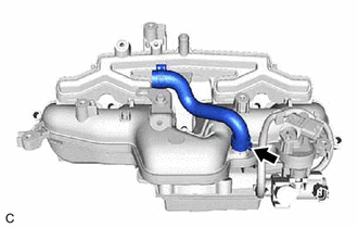
REMOVE NO. 2 VENTILATION HOSE
-
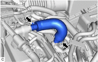
Slide the 2 clips and remove the No. 2 ventilation hose from the intake manifold and cylinder head cover sub-assembly.
-
-
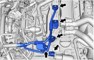
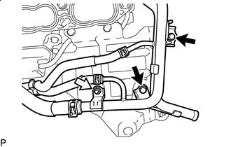
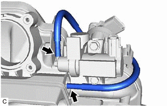
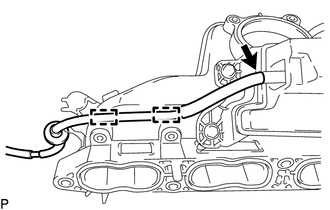
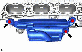
REMOVE NO. 2 WATER BY-PASS PIPE
-
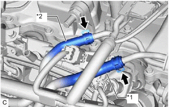
*1 No. 1 Turbo Water Hose *2 No. 2 Turbo Water Hose Slide the 2 clips and disconnect the No. 1 turbo water hose and No. 2 turbo water hose from the No. 2 water by-pass pipe.
-
Remove the 2 bolts and No. 2 water by-pass pipe from the intake manifold.
-
-
DISCONNECT INLET HEATER WATER HOSE A
-
DISCONNECT OUTLET HEATER WATER HOSE A
-
DISCONNECT ENGINE WIRE
-
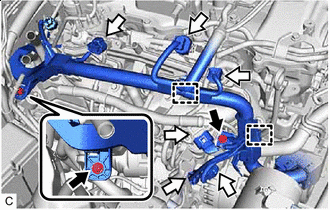

Bolt 
Connector Remove the 2 bolts.
-
Disconnect the 6 connectors.
-
Disengage the 2 clamps.
-
Disconnect the 5 connectors.
-
-
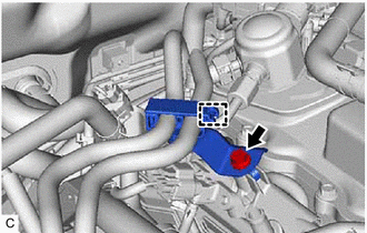
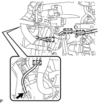
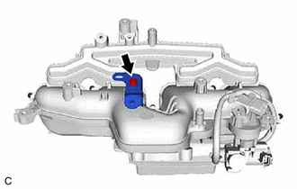
DISCONNECT NO. 3 WATER BY-PASS HOSE
-
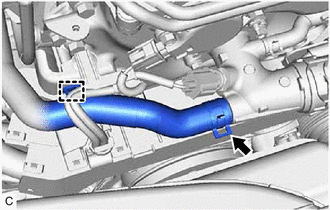
Disengage the clamp.
-
Slide the clip and disconnect the No. 3 water by-pass hose from the water outlet sub-assembly.
-
-
DISCONNECT NO. 2 VACUUM TRANSMITTING HOSE ASSEMBLY
-
Disengage the clamp from the cylinder head cover sub-assembly.
-
Disconnect the No. 2 vacuum transmitting hose assembly from the vacuum pump assembly.
-
-
DISCONNECT VACUUM TRANSMITTING HOSE ASSEMBLY
-
Disengage the 4 clamps and disconnect the vacuum transmitting hose assembly from the cylinder head cover sub-assembly.
-
Disconnect the vacuum transmitting hose assembly from the waste gate valve actuator with bracket assembly.
-
-
DISCONNECT INLET HEATER WATER HOSE B
-
Slide the clip and disconnect the inlet heater water hose B from the No. 5 water by-pass pipe.
-
-
REMOVE INTAKE MANIFOLD
-
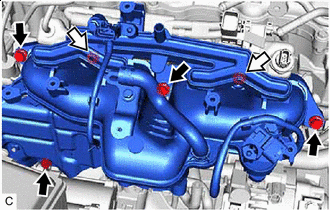
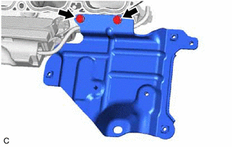
Bolt Nut Remove the 4 bolts, 2 nuts and intake manifold from the cylinder head sub-assembly and cylinder block sub-assembly.
-
Bolt Nut Remove the 2 bolts, nut and No. 5 water by-pass pipe from the intercooler support bracket sub-assembly.
-
Remove the 2 bolts and intercooler support bracket sub-assembly from the intake manifold.
Note
Align the intercooler support bracket sub-assembly with its marked original position and remove it.
-
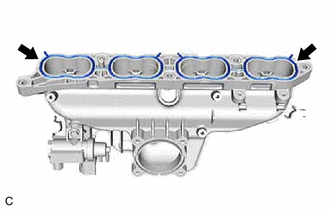
Remove the 2 intake manifold gaskets from the intake manifold.
-
-
REMOVE NO. 2 TURBO PRESSURE SENSOR
-
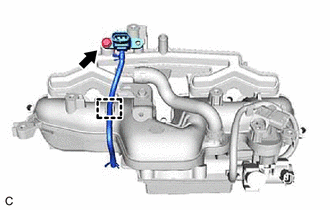
Disengage the No. 1 vacuum transmitting hose assembly from the intake manifold.
-
Remove the bolt and No. 2 turbo pressure sensor from the intake manifold.
-
-
REMOVE NO. 2 FUEL VAPOR FEED HOSE
-
Slide the clip and remove the No. 2 fuel vapor feed hose from the intake manifold.
-
-
REMOVE BRACKET
-
Remove the bolt and bracket from the intake manifold.
-
-
REMOVE NO. 3 VACUUM TRANSMITTING HOSE ASSEMBLY
-
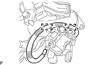
Disengage the 2 clamps.
-
Remove the No. 3 vacuum transmitting hose assembly from the vacuum surge tank and vacuum regulating valve assembly.
-
-
REMOVE NO. 1 TURBO PRESSURE SENSOR
-
Remove the bolt and No. 1 turbo pressure sensor from the intake manifold.
-
-
REMOVE VACUUM REGULATING VALVE ASSEMBLY
-
Remove the 2 bolts and vacuum regulating valve assembly from the intake manifold.
-
-
REMOVE NO. 4 VACUUM TRANSMITTING HOSE ASSEMBLY
-
Disengage the 2 clamps and remove the No. 4 vacuum transmitting hose assembly from the vacuum surge tank.
-
-
REMOVE VACUUM SURGE TANK
-
Remove the 3 bolts and vacuum surge tank from the intake manifold.
-