THROTTLE BODY INSTALLATION
PROCEDURE
-
INSTALL THROTTLE BODY GASKET
-
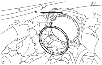
*a Protrusion *b Groove Install a new throttle body gasket to the intake air surge tank assembly with the protrusion of the throttle body gasket oriented as shown in the illustration.
-
-
INSTALL THROTTLE BODY WITH MOTOR ASSEMBLY
Tech Tips
Perform "Inspection After Repair" after replacing the throttle body with motor assembly.
-
w/ Canister Pump Module:
-
w/o Canister Pump Module:
-
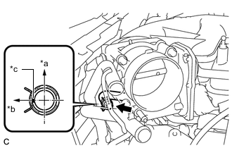
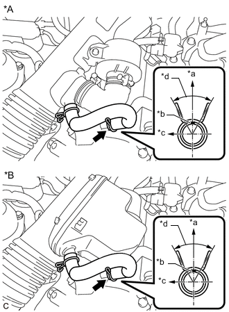
*a Top *b Rear of Vehicle *c Paint Mark Connect the water by-pass hose to the throttle body with motor assembly and slide the clip to secure it.
Note
Make sure to position the clip as shown in the illustration.
-
Install the throttle body with motor assembly to the intake air surge tank assembly with the 4 bolts.
- Torque:
- 10 N*m { 102 kgf*cm, 7 ft.*lbf }
-
Connect the throttle body with motor assembly connector.
-
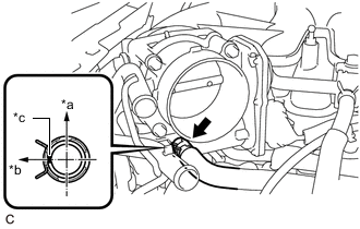
*a Top *b Rear of Vehicle *c Paint Mark Connect the No. 16 water by-pass hose to the throttle body with motor assembly and slide the clip to secure it.
Note
Make sure to position the clip as shown in the illustration.
-
-
INSTALL AIR CLEANER CAP WITH AIR CLEANER HOSE
-
Connect the air cleaner cap with air cleaner hose to the throttle body with motor assembly.
-
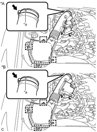
*A w/ Intake Air Sound Creator *B w/o Intake Air Sound Creator *a Protrusion Install the air cleaner cap with air cleaner hose with the 4 clamps.
-
Tighten the hose clamp.
- Torque:
- 4.0 N*m { 41 kgf*cm, 35 in.*lbf }
Note
Fit the protrusion on the air cleaner hose into the hole of the hose clamp on the throttle body with motor assembly side.
-
Engage the clamp to connect the fuel vapor feed hose to the air cleaner cap with air cleaner hose.
-
Connect the wire harness clamp to the air cleaner cap with air cleaner hose.
-
Connect the mass air flow meter sub-assembly connector.
-
*A w/ Intake Air Sound Creator *B w/o Intake Air Sound Creator *a Top *b Paint Mark *c Front of Vehicle *d 60°(Claw of Clip Location) Connect the No. 2 ventilation hose to the cylinder head cover sub-assembly and slide the clip to secure it.
Note
Make sure to position the clip as shown in the illustration.
-
-
INSTALL INTAKE AIR SOUND CREATOR (w/ INTAKE AIR SOUND CREATOR)
Tech Tips
Only perform this procedure when replacement of the intake air sound creator is necessary.
-
Connect the intake air sound creator to the air cleaner cap with air cleaner hose.
-
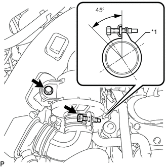
*1 Air Cleaner Hose Install the bolt and tighten the hose clamp.
- Torque:
- 5.0 N*m { 51 kgf*cm, 44 in.*lbf }
Note
Make sure to position the hose clamp as shown in the illustration.
-
-
ADD ENGINE COOLANT
-
INSPECT FOR COOLANT LEAK
-
INSTALL ENGINE ROOM SIDE COVER
-
INSTALL V-BANK COVER SUB-ASSEMBLY
-
PERFORM INITIALIZATION
Note
-
Be sure to perform this procedure after removing and reinstalling the throttle body with motor assembly or any throttle body with motor assembly components.
-
Perform the following procedure after replacing the throttle body with motor assembly or any throttle body with motor assembly components. The following procedure should also be performed if the throttle body with motor assembly is cleaned.
-
Connect the GTS to the DLC3.
-
Clear the DTCs.
-
w/ Canister Pump Module:
-
w/o Canister Pump Module:
-
-
Perform "Inspection After Repair".
-
w/ Canister Pump Module:
-
w/o Canister Pump Module:
-
-
Start the engine and check that the MIL is not illuminated. After the engine is warmed up, check that the idle speed is within the specified range with the A/C switch off.
Standard Idle Speed 600 to 700 rpm Note
-
Be sure to perform this step with all accessories off.
-
Make sure that the shift lever is in P or N.
-
-
Enter the following menus: Powertrain / Engine / Data List / Throttle Position Sensor No.1 Voltage %.
Powertrain > Engine > Data ListTester Display Throttle Position Sensor No.1 Voltage % -
According to the display on the GTS, read the Data List while fully depressing the accelerator pedal and check that the value is 60% or higher.
-
Perform a road test and confirm that there are no abnormalities.
-