CAMSHAFT OIL CONTROL SOLENOID INSTALLATION
PROCEDURE
-
INSTALL CAMSHAFT TIMING OIL CONTROL SOLENOID ASSEMBLY (for Intake Side of Bank 1)
-
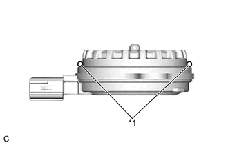
*1 O-ring Apply engine oil to a new O-ring and install it to the camshaft timing oil control solenoid assembly as shown in the illustration.
Note
Do not damage the O-ring.
-
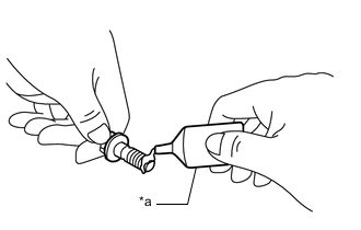
*a Adhesive Apply adhesive to 2 or 3 threads of 2 new bolts.
Adhesive Toyota Genuine Adhesive 1324, Three Bond 1324 or equivalent -
Install the camshaft timing oil control solenoid assembly to the timing chain cover assembly with the 2 bolts.
- Torque:
- 10 N*m { 102 kgf*cm, 7 ft.*lbf }
Note
-
If the camshaft timing oil control solenoid assembly has been struck or dropped, replace it.
-
Make sure that the O-ring is not cracked or moved out of place when installing the camshaft timing oil control solenoid assembly.
-
Connect the camshaft timing oil control solenoid assembly connector.
-
-
INSTALL CAMSHAFT TIMING OIL CONTROL SOLENOID ASSEMBLY (for Exhaust Side of Bank 1)
-
*1 O-ring Apply engine oil to a new O-ring and install it to the camshaft timing oil control solenoid assembly as shown in the illustration.
Note
Do not damage the O-ring.
-
*a Adhesive Apply adhesive to 2 or 3 threads of 2 new bolts.
Adhesive Toyota Genuine Adhesive 1324, Three Bond 1324 or equivalent -
Install the camshaft timing oil control solenoid assembly to the timing chain cover assembly with the 2 bolts.
- Torque:
- 10 N*m { 102 kgf*cm, 7 ft.*lbf }
Note
-
If the camshaft timing oil control solenoid assembly has been struck or dropped, replace it.
-
Make sure that the O-ring is not cracked or moved out of place when installing the camshaft timing oil control solenoid assembly.
-
Connect the camshaft timing oil control solenoid assembly connector.
-
Install the wire harness clamp bracket to the timing chain cover assembly with the bolt.
- Torque:
- 10 N*m { 102 kgf*cm, 7 ft.*lbf }
-
-
INSTALL CAMSHAFT TIMING OIL CONTROL SOLENOID ASSEMBLY (for Intake Side of Bank 2)
-
*1 O-ring Apply engine oil to a new O-ring and install it to the camshaft timing oil control solenoid assembly as shown in the illustration.
Note
Do not damage the O-ring.
-
*a Adhesive Apply adhesive to 2 or 3 threads of 2 new bolts.
Adhesive Toyota Genuine Adhesive 1324, Three Bond 1324 or equivalent -
Install the camshaft timing oil control solenoid assembly to the timing chain cover assembly with the 2 bolts.
- Torque:
- 10 N*m { 102 kgf*cm, 7 ft.*lbf }
Note
-
If the camshaft timing oil control solenoid assembly has been struck or dropped, replace it.
-
Make sure that the O-ring is not cracked or moved out of place when installing the camshaft timing oil control solenoid assembly.
-
Connect the camshaft timing oil control solenoid assembly connector.
-
-
INSTALL CAMSHAFT TIMING OIL CONTROL SOLENOID ASSEMBLY (for Exhaust Side of Bank 2)
-
*1 O-ring Apply engine oil to a new O-ring and install it to the camshaft timing oil control solenoid assembly as shown in the illustration.
Note
Do not damage the O-ring.
-
*a Adhesive Apply adhesive to 2 or 3 threads of 2 new bolts.
Adhesive Toyota Genuine Adhesive 1324, Three Bond 1324 or equivalent -
Install the camshaft timing oil control solenoid assembly to the timing chain cover assembly with the 2 bolts.
- Torque:
- 10 N*m { 102 kgf*cm, 7 ft.*lbf }
Note
-
If the camshaft timing oil control solenoid assembly has been struck or dropped, replace it.
-
Make sure that the O-ring is not cracked or moved out of place when installing the camshaft timing oil control solenoid assembly.
-
Connect the camshaft timing oil control solenoid assembly connector.
-
Install the wire harness clamp bracket to the timing chain cover assembly with the bolt.
- Torque:
- 10 N*m { 102 kgf*cm, 7 ft.*lbf }
-
-
INSTALL WATER OUTLET SUB-ASSEMBLY
-
Install a new O-ring to the No. 1 water outlet pipe.
Tech Tips
Apply water to the O-ring.
-
Install the water outlet sub-assembly to the timing chain cover assembly with the 2 bolts.
- Torque:
- 21 N*m { 214 kgf*cm, 15 ft.*lbf }
Note
Make sure that the O-ring is not cracked or moved out of place when installing the water outlet sub-assembly.
-
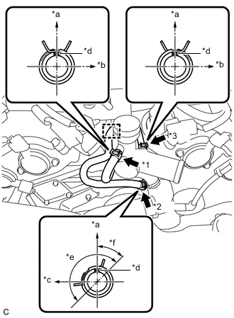
*1 No. 6 Water By-pass Hose *2 No. 15 Water By-pass Hose *3 No. 2 Water By-pass Hose *a Up *b Left of Vehicle *c Front of Vehicle *d Paint Mark *e Claw of Clip Location *f 45° w/o Oil Cooler:
-
Connect the No. 2 water by-pass hose to the water outlet sub-assembly and slide the clip to secure it.
Note
Make sure to position the clip as shown in the illustration.
-
Engage the clamp to connect the No. 15 water by-pass hose to the water outlet sub-assembly.
-
Connect the No. 15 water by-pass hose to the water inlet sub-assembly with thermostat and slide the clip to secure it.
Note
Make sure to position the clip as shown in the illustration.
-
Connect the No. 6 water by-pass hose to the water outlet sub-assembly and slide the clip to secure it.
Note
Make sure to position the clip as shown in the illustration.
-
-
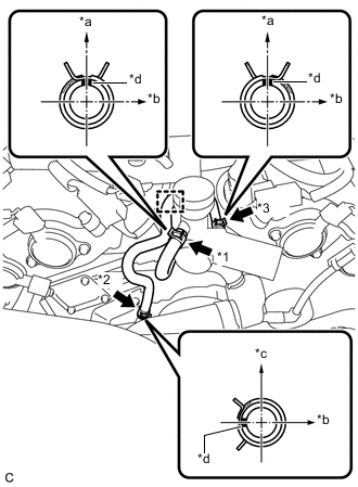
*1 No. 6 Water By-pass Hose *2 No. 14 Water By-pass Hose *3 No. 2 Water By-pass Hose *a Up *b Left of Vehicle *c Rear of Vehicle *d Paint Mark w/ Oil Cooler:
-
Connect the No. 2 water by-pass hose to the water outlet sub-assembly and slide the clip to secure it.
Note
Make sure to position the clip as shown in the illustration.
-
Engage the clamp to connect the No. 14 water by-pass hose to the water outlet sub-assembly.
-
Connect the No. 14 water by-pass hose to the No. 1 water by-pass pipe and slide the clip to secure it.
Note
Make sure to position the clip as shown in the illustration.
-
Connect the No. 6 water by-pass hose to the water outlet sub-assembly and slide the clip to secure it.
Note
Make sure to position the clip as shown in the illustration.
-
-
-
INSTALL NO. 1 RADIATOR HOSE
-
ADD ENGINE COOLANT
-
INSPECT FOR COOLANT LEAK
-
INSPECT FOR ENGINE OIL LEAK
-
INSTALL COOL AIR INTAKE DUCT SEAL
-
INSTALL ENGINE ROOM SIDE COVER
-
INSTALL V-BANK COVER SUB-ASSEMBLY