STEERING LINKAGE INSTALLATION

PROCEDURE
-
INSTALL POWER STEERING LINK ASSEMBLY
-
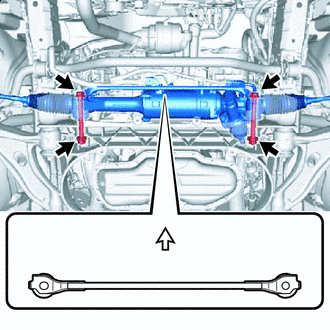

Upward Install the power steering link assembly with the 2 bolts, No. 1 steering rack housing bracket and 2 nuts.
- Torque:
- 117.6 N*m { 1199 kgf*cm, 87 ft.*lbf }
Note
Be sure to install the No. 1 steering rack housing bracket in the correct direction.
-
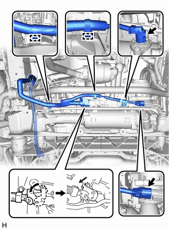
Connect the 2 wire harness clamps to the power steering link assembly.
-
Connect the 3 wire harness connectors to the power steering link assembly.
Tech Tips
When connecting the connector with lock lever, return the lock lever to its original position and securely push in the lock of the lock lever as shown in the illustration.
-
-
CONNECT TIE ROD ASSEMBLY LH
-
Connect the tie rod assembly LH to the front lower ball joint assembly with the nut.
- Torque:
- 65 N*m { 663 kgf*cm, 48 ft.*lbf }
Note
Prevent oil from adhering to the threaded and tapered parts.
-
Install a new clip.
Note
Further tighten the nut up to 60° if the holes for the clip are not aligned.
-
-
CONNECT TIE ROD ASSEMBLY RH
Tech Tips
Perform the same procedure as for the LH side.
-
INSTALL STEERING SLIDING WITH SHAFT YOKE SUB-ASSEMBLY
-
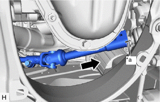
*a Matchmark Align the matchmarks on the steering sliding with shaft yoke sub-assembly with the matchmarks on the power steering link assembly.
-
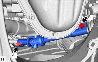
Install the bolt (B) and tighten the bolt (A).
- Torque:
- 35.3 N*m { 360 kgf*cm, 26 ft.*lbf }
-
-
INSTALL FRONT LOWER SUSPENSION MEMBER PROTECTOR
for 2GR-FSE:
for 8AR-FTS:
-
INSTALL FRONT UPPER NO. 2 SUSPENSION MEMBER
for 2GR-FSE:
for 8AR-FTS:
-
INSTALL SUSPENSION TOWER DAMPER
w/ Performance Damper:
-
INSTALL NO. 2 ENGINE UNDER COVER (w/ No.2 Engine Under Cover)
for 2GR-FSE:
for 8AR-FTS:
-
INSTALL FRONT SUSPENSION MEMBER BRACE
for 2GR-FSE:
for 8AR-FTS:
-
INSTALL REAR ENGINE UNDER COVER LH
for 2GR-FSE:
for 8AR-FTS:
-
INSTALL REAR ENGINE UNDER COVER RH
Tech Tips
Perform the same procedure as for the LH side.
-
INSTALL NO. 1 ENGINE UNDER COVER ASSEMBLY
for 2GR-FSE:
for 8AR-FTS:
-
INSTALL FRONT WHEELS
-
ALIGN FRONT WHEELS FACING STRAIGHT AHEAD
-
CONNECT CABLE TO NEGATIVE BATTERY TERMINAL
Note
When disconnecting the cable, some systems need to be initialized after the cable is reconnected.
-
INSPECT AND ADJUST FRONT WHEEL ALIGNMENT
-
ROTATION ANGLE SENSOR INITIALIZATION AND TORQUE SENSOR ZERO POINT CALIBRATION
-
PERFORM VARIABLE GEAR RATIO STEERING SYSTEM CALIBRATION (w/ VGRS)