AUTOMATIC TRANSMISSION SYSTEM (for 1UR-FE) Shift Paddle Switch Circuit
DESCRIPTION
When the shift lever is in S, the shift range can be changed using the shift paddle switches. It is also possible to select the shift range when the vehicle is being driven with the shift lever in D by operating the shift paddle switches.
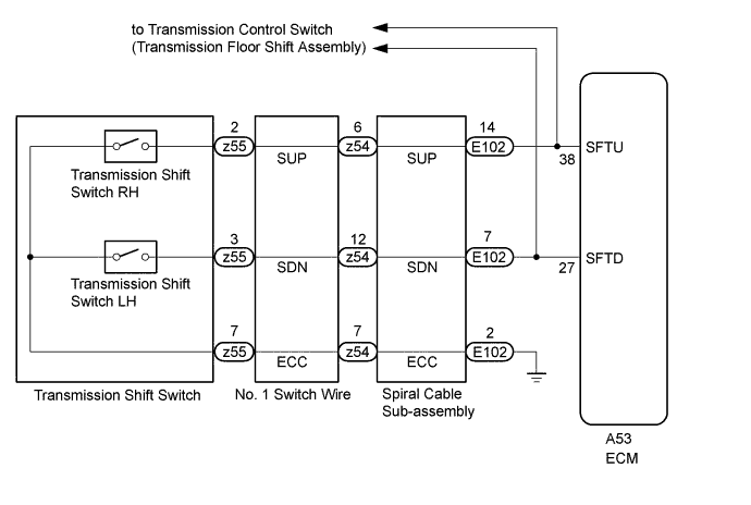
WIRING DIAGRAM
INSPECTION PROCEDURE
PROCEDURE
-
CHECK HARNESS AND CONNECTOR (SPIRAL CABLE - BODY GROUND)
-
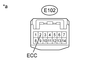
Text in Illustration *a Front view of wire harness connector
(to Spiral Cable with Sensor Sub-assembly)
Disconnect the spiral cable connector.
-
Measure the resistance according to the value(s) in the table below.
Standard Resistance Tester Connection Condition Specified Condition E102-2 (ECC) - Body ground Always Below 1 Ω
NG 
REPAIR OR REPLACE HARNESS OR CONNECTOR
OK 
-
-
INSPECT SPIRAL CABLE WITH SENSOR SUB-ASSEMBLY
-
Remove the spiral cable with sensor sub-assembly Click here.
-
Set the spiral cable to the center position.
-
Measure the resistance between the terminals of the spiral cable.
-
After setting the spiral cable to the center position, rotate the spiral cable 2.5 times clockwise and measure the resistance. Then rotate the spiral cable 2.5 times counterclockwise and measure the resistance.
-
After setting the spiral cable to the center position, rotate the spiral cable 2.5 times clockwise. Then while rotating the spiral cable 5 times counterclockwise, measure the resistance.
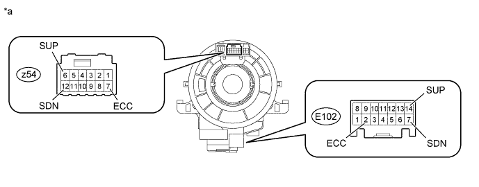
Standard Resistance Tester Connection Condition Specified Condition z54-6 (SUP) - E102-14 (SUP) Always Below 1 Ω z54-12 (SDN) - E102-7 (SDN) Always Below 1 Ω z54-7 (ECC) - E102-2 (ECC) Always Below 1 Ω Note
As the spiral cable may break, do not rotate the spiral cable more than the specified amount.
Text in Illustration *a Component without harness connected
(Spiral Cable with Sensor Sub-assembly)
-
NG
REPLACE SPIRAL CABLE WITH SENSOR SUB-ASSEMBLY Click here
OK
-
-
INSPECT TRANSMISSION SHIFT SWITCH ASSEMBLY RH (+)
-
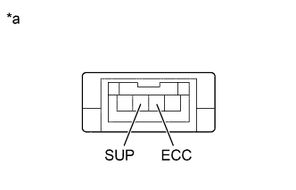
Text in Illustration *a Component without harness connected
(Transmission Shift Switch Assembly RH (+))
Remove the transmission shift switch assembly RH (+) Click here.
-
Measure the resistance according to the value(s) in the table below.
Standard Resistance Tester Connection Switch Condition Specified Condition SUP - ECC "+" shift paddle operated and held (up-shift) Below 2.5 Ω SUP - ECC "+" shift paddle not operated (up-shift) 1 MΩ or higher
NG
REPLACE TRANSMISSION SHIFT SWITCH ASSEMBLY RH (+) Click here
OK
-
-
INSPECT TRANSMISSION SHIFT SWITCH ASSEMBLY LH (-)
-
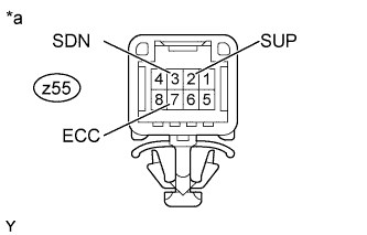
Text in Illustration *a Front view of wire harness connector
(Transmission Shift Switch Assembly LH (-))
Disconnect the transmission shift switch assembly LH (-) connector.
-
Measure the resistance according to the value(s) in the table below.
Standard Resistance Tester Connection Switch Condition Specified Condition z55-2 (SUP) - z55-7 (ECC) "+" shift paddle operated and held (up-shift) Below 2.5 Ω z55-3 (SDN) - z55-7 (ECC) "-" shift paddle operated and held (down-shift) Below 2.5 Ω z55-2 (SUP) - z55-7 (ECC) "+" shift paddle not operated (up-shift) 1 MΩ or higher z55-3 (SDN) - z55-7 (ECC) "-" shift paddle not operated (down-shift) 1 MΩ or higher
NG
REPLACE TRANSMISSION SHIFT SWITCH ASSEMBLY LH (-) Click here
OK
-
-
INSPECT NO. 1 SWITCH WIRE
-
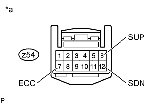
Text in Illustration *a Component without harness connected
(No. 1 Switch Wire)
Disconnect the No. 1 switch wire connector.
-
Measure the resistance according to the value(s) in the table below.
Standard Resistance Tester Connection Switch Condition Specified Condition z54-6 (SUP) - z54-7 (ECC) "+" shift paddle operated and held (up-shift) Below 2.5 Ω z54-12 (SDN) - z54-7 (ECC) "-" shift paddle operated and held (down-shift) Below 2.5 Ω z54-6 (SUP) - z54-7 (ECC) "+" shift paddle not operated (up-shift) 1 MΩ or higher z54-12 (SDN) - z54-7 (ECC) "-" shift paddle not operated (down-shift) 1 MΩ or higher
NG
REPLACE NO. 1 SWITCH WIRE Click here
OK
-
-
CHECK HARNESS AND CONNECTOR (SPIRAL CABLE - ECM)
-
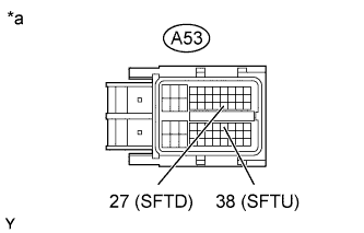
Text in Illustration *a Front view of wire harness connector
(to ECM)
Disconnect the ECM connector.
-
Disconnect the transmission control switch (transmission floor shift assembly) connector.
-
Measure the resistance according to the value(s) in the table below.
Standard Resistance Tester Connection Switch Condition Specified Condition A53-38 (SFTU) - Body ground "+" shift paddle operated and held (up-shift) Below 2.5 Ω A53-27 (SFTD) - Body ground "-" shift paddle operated and held (down-shift) Below 2.5 Ω A53-38 (SFTU) - Body ground "+" shift paddle not operated (up-shift) 1 MΩ or higher A53-27 (SFTD) - Body ground "-" shift paddle not operated (down-shift) 1 MΩ or higher
NG
REPAIR OR REPLACE HARNESS OR CONNECTOR
OK 
REPLACE ECM Click here
-