- Click here
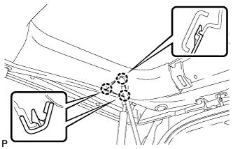
INSTALL BACK DOOR MOTOR UNIT
-
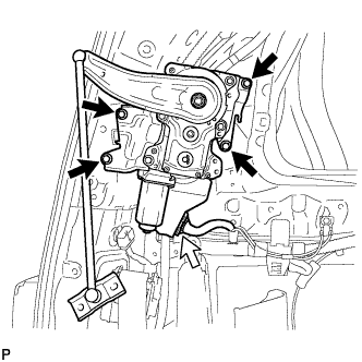
Install the back door motor unit with the 4 bolts.
14 N*m 143 kgf*cm 10 ft.*lbf -
Connect the connector.
-
- Click here
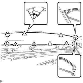
INSTALL UPPER ROOF SIDE INNER GARNISH LH
-
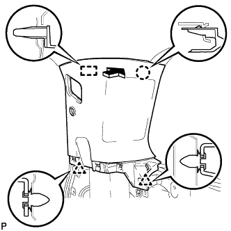
Engage the guide, claw and 2 clips to install the upper roof side inner garnish LH.
-
- Click here
CONNECT REAR NO. 2 SEAT OUTER BELT ASSEMBLY LH
Tip:Use the same procedure for the RH side and LH side (Click here).
- Click here
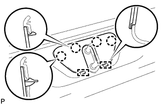
INSTALL REAR SEAT HOOK SUB-ASSEMBLY LH
Tip:Use the same procedure for the RH side and LH side (Click here).
- Click here
CONNECT POWER BACK DOOR ROD
-
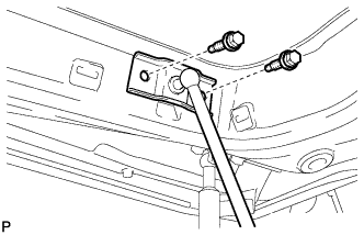
Install the power back door rod with the 2 bolts.
30 N*m 306 kgf*cm 22 ft.*lbf
-
- Click here
INSTALL REAR WINDOW SIDE GARNISH LH
-
Engage the 3 clips and 2 claws to install the rear window side garnish LH.
-
- Click here
INSTALL BACK DOOR NO. 2 SERVICE HOLE COVER
-
Engage the 3 claws to install the back door No. 2 service hole cover.
-
- Click here
INSTALL BACK DOOR CENTER GARNISH
-
Engage the 6 clips and 4 claws to install the back door center garnish.
-
- Click here
INSTALL REAR QUARTER TRIM PANEL ASSEMBLY LH
-
Engage the 2 guides, 8 claws and 15 clips, and install the rear quarter trim panel assembly LH.
-
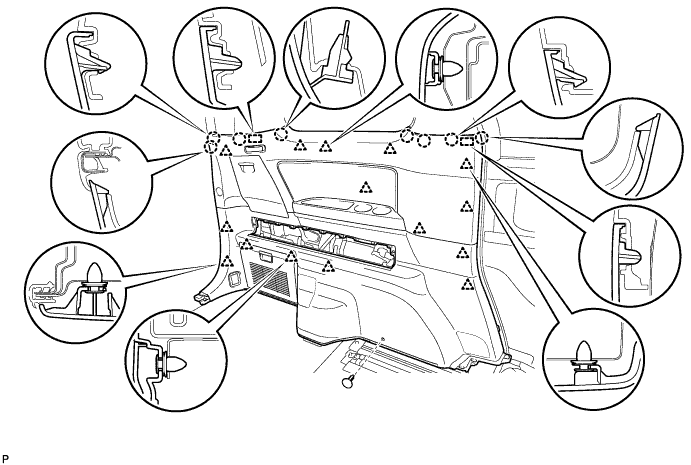
Install the clip(A).
-
- Click here
CONNECT REAR NO. 1 SEAT OUTER BELT ASSEMBLY (for 60/40 Split Seat Type)
Tip:Use the same procedure for the RH side and LH side (Click here).
- Click here
INSTALL LUGGAGE COMPARTMENT TRIM INNER COVER (for 60/40 Split Seat Type)
Tip:Use the same procedure for the RH side and LH side (Click here).
- Click here
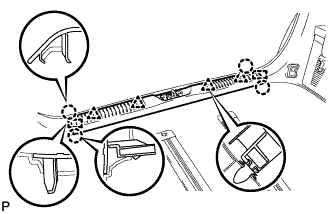
INSTALL DECK SIDE GARNISH LH
-
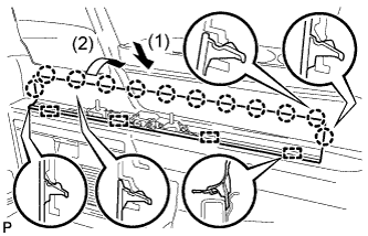
Engage the 4 guides and 12 claws to install the deck side garnish LH as shown in the illustration.
-
- Click here
INSTALL ROPE HOOK ASSEMBLY
Tip:Use the same procedure for the RH side and LH side (Click here).
- Click here
INSTALL NO. 2 LUGGAGE COMPARTMENT TRIM HOOK
Tip:Use the same procedure for the No. 2 luggage compartment trim hook and No. 1 luggage compartment trim hook (Click here).
- Click here
INSTALL REAR NO. 2 SEAT ASSEMBLY LH
Tip:Use the same procedure for the RH side and LH side (Click here).
- Click here
INSTALL NO. 1 SEAT TRACK LOCK PLATE COVER
Tip:Use the same procedure for the RH side and LH side (Click here).
- Click here
INSTALL UPPER SEAT TRACK RAIL COVER LH
Tip:Use the same procedure for the RH side and LH side (Click here).
- Click here
INSTALL RECLINING ADJUSTER RELEASE HANDLE LH
Tip:Use the same procedure for the RH side and LH side (Click here).
- Click here
INSTALL BACK DOOR SCUFF PLATE
-
Engage the 2 guides, 4 clips and 4 claws to install the back door scuff plate.
-
- Click here
INSTALL BACK DOOR STRIKER COVER
-
Engage the 2 guides and 4 claws to install the back door striker cover.
-
- Click here
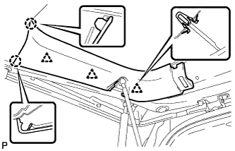
CONNECT NO. 1 SLIDE DOOR WEATHERSTRIP LH
-
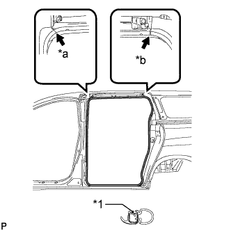
Align the alignment marks on the weatherstrip with the protruding portions on the body indicated by the arrows in the illustration, and install the No. 1 slide door weatherstrip LH.
Table 1. Text in Illustration *1 Alignment Mark *a White *b Light Blue Note:After installation, check that the corners fit correctly.
-
- Click here
INSTALL REAR DOOR SCUFF PLATE LH
Tip:Use the same procedure for the RH side and LH side (Click here).