SLIDE DOOR REASSEMBLY

-
INSTALL SLIDE DOOR LOWER ROLLER ASSEMBLY
-
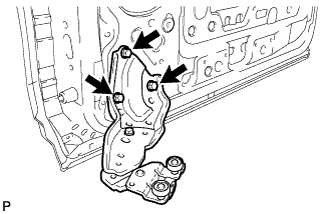
Install the slide door lower roller assembly with the 3 bolts.
- Torque:
- 20 N*m { 204 kgf*cm, 15 ft.*lbf }
-
-
INSTALL SLIDE DOOR UPPER ROLLER ASSEMBLY
-
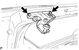
Install the slide door upper roller assembly with the 2 bolts.
- Torque:
- 13 N*m { 133 kgf*cm, 10 ft.*lbf }
-
-
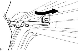
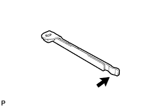
INSTALL SLIDE DOOR CENTER HINGE ASSEMBLY
-
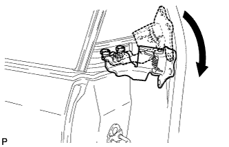
Install the slide door center hinge assembly as shown in the illustration.
-
Move the slide door center hinge assembly to the rear of the slide rail.
-
-
INSTALL SLIDE DOOR (w/o Power Slide Door)
-
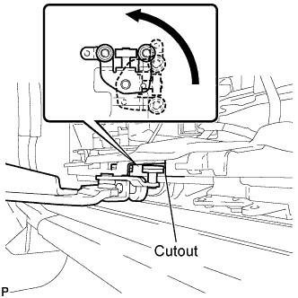
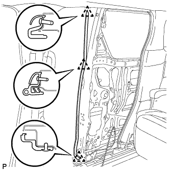
Turn the roller of the slide door lower roller assembly as shown in the illustration and slide it in through the cutout of the slide door lower rail to install the slide door.
Note
-
To prevent damage, when installing the slide door, make sure that there are enough people available to hold it securely.
-
Hold the slide door until the slide door center hinge assembly is installed because the slide door will be unstable until the hinge is installed.
-
-
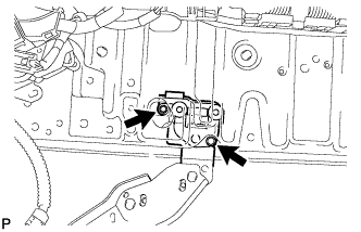
Install the slide door upper roller assembly as shown in the illustration.
-
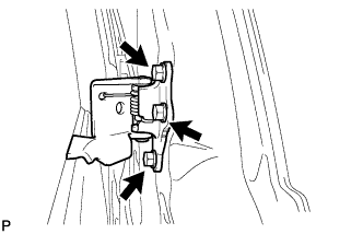
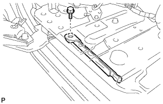
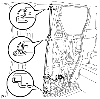
Install the slide door center hinge assembly with the 3 bolts.
- Torque:
- 20 N*m { 204 kgf*cm, 15 ft.*lbf }
-
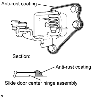
Using a brush, apply anti-rust coating to the slide door center hinge assembly as shown in the illustration.
-
-
INSTALL SLIDE DOOR (w/ Power Slide Door)
-
Turn the roller of the slide door lower roller assembly as shown in the illustration and slide it in through the cutout of the slide door lower rail to install the slide door.
Note
-
To prevent damage, when installing the slide door, make sure that there are enough people available to hold it securely.
-
Hold the slide door until the slide door center hinge assembly is installed because the slide door will be unstable until the hinge is installed.
-
-
Install the slide door upper roller assembly as shown in the illustration.
-
Install the slide door center hinge assembly with the 3 bolts.
- Torque:
- 20 N*m { 204 kgf*cm, 15 ft.*lbf }
-
Using a brush, apply anti-rust coating to the slide door center hinge assembly as shown in the illustration.
-
Connect the slide door lower roller assembly with the 2 bolts.
- Torque:
- 7.8 N*m { 80 kgf*cm, 69 in.*lbf }
-
-
INSTALL SLIDE DOOR LOWER RAIL PLATE
-
Apply MP grease to the slide door lower rail plate.
-
Install the slide door lower rail plate with the bolt.
- Torque:
- 13 N*m { 133 kgf*cm, 10 ft.*lbf }
-
-
INSTALL SLIDE DOOR UPPER RAIL CUSHION
-
Install the slide door upper rail cushion with the clip.
-
-
INSTALL NO. 1 SIDE MUDGUARD BRACKET (for Standard)
Tech Tips
Use the same procedure for the RH side and LH side Click here.
-
INSTALL SLIDE DOOR MUDGUARD SUB-ASSEMBLY (for Standard)
Tech Tips
Use the same procedure for the RH side and LH side Click here.
-
INSTALL NO. 1 SIDE MUDGUARD BRACKET (for Sport Package)
Tech Tips
Use the same procedure for the RH side and LH side Click here.
-
INSTALL SLIDE DOOR MUDGUARD SUB-ASSEMBLY (for Sport Package)
Tech Tips
Use the same procedure for the RH side and LH side Click here.
-
INSTALL SLIDE DOOR UPPER CUSHION
-
Engage the claw and install the slide door upper cushion.
-
-
INSTALL SLIDE DOOR LOWER CUSHION
-
Engage the claw and install the slide door lower cushion.
-
-
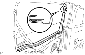
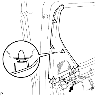
INSTALL CENTER DOOR REAR WEATHERSTRIP
-
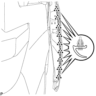
Engage the 9 clips to install the center door rear weatherstrip.
-
-
INSTALL SLIDE DOOR FULL OPEN STOP LOCK ASSEMBLY
-
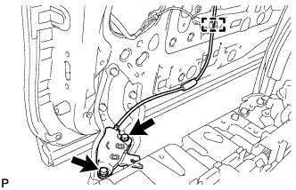
Insert the 2 bolts and slide door full open stop lock assembly.
- Torque:
- 19 N*m { 194 kgf*cm, 14 ft.*lbf }
-
Engage the clamp.
-
-
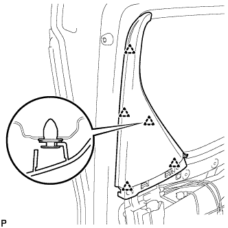
INSTALL SLIDE DOOR NO. 3 WEATHERSTRIP
-
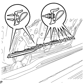
Engage the 8 clips to install the slide door No. 3 weatherstrip.
-
-
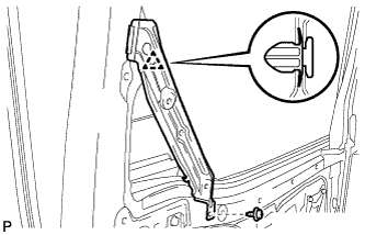
INSTALL CENTER PILLAR UPPER END WEATHERSTRIP (w/o Power Slide Door)
-
Engage the 3 clips and install the center pillar upper end weatherstrip.
-
-
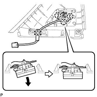
INSTALL POWER SLIDE DOOR TOUCH SENSOR ASSEMBLY (w/ Power Slide Door)
-
Engage the 3 clips and claw, and install the power slide door touch sensor assembly.
-
Engage the clamp.
-
-
INSTALL REAR DOOR OUTSIDE HANDLE FRAME SUB-ASSEMBLY
-
Apply MP grease to the sliding parts on the rear door outside handle frame sub-assembly.
-
Engage the claw to install the rear door outside handle frame sub-assembly.
-
Using a T30 "TORX" socket wrench, install the rear door outside handle frame sub-assembly with the screw.
- Torque:
- 7.0 N*m { 71 kgf*cm, 62 in.*lbf }
-
-
INSTALL REAR DOOR REAR OUTSIDE HANDLE PAD
-
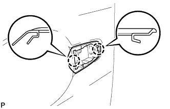
Engage the 2 claws to install the rear door rear outside handle pad.
-
-
INSTALL REAR DOOR FRONT OUTSIDE HANDLE PAD
-
Engage the 3 claws to install the rear door front outside handle pad.
-
-
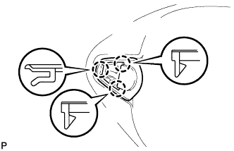
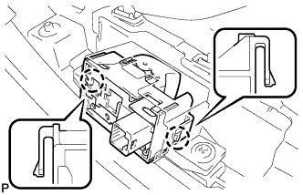
INSTALL REAR DOOR OUTSIDE HANDLE ASSEMBLY
-
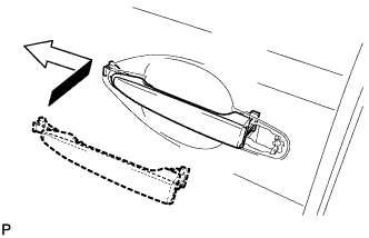
Insert the front end of the rear door outside handle assembly into the rear door outside handle frame.
Note
If the bellcrank lever is not pulled and held when installing the outside handle, the bellcrank lever will interfere with the outside handle and the release plate may be damaged.
-
Insert the rear end of the rear door outside handle assembly into the rear door outside handle frame. Next, slide the rear door outside handle assembly toward the front of the vehicle to install it.
-
-
INSTALL REAR DOOR OUTSIDE HANDLE COVER
-
Using a T30 "TORX" socket wrench, install the rear door outside handle cover with the screw.
- Torque:
- 7.0 N*m { 71 kgf*cm, 62 in.*lbf }
-
Install the hole plug.
-
-
INSTALL REAR DOOR LOCK ASSEMBLY
-
Apply MP grease to the sliding parts of the rear door lock assembly.
-
Using a T30 "TORX" socket wrench, install the rear door lock assembly with the 3 screws.
- Torque:
- 8.0 N*m { 82 kgf*cm, 71 in.*lbf }
-
Install the bolt.
-
Engage the clamp.
-
-
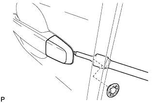
INSTALL SLIDE DOOR FRONT LOCK ASSEMBLY
-
Apply MP grease to the sliding parts of the slide door front lock assembly.
-
At the time of reuse
-
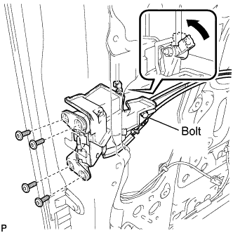
Using a T30 "TORX" socket wrench, install the slide door front lock assembly with the 4 screws.
- Torque:
- 5.5 N*m { 56 kgf*cm, 49 in.*lbf }
-
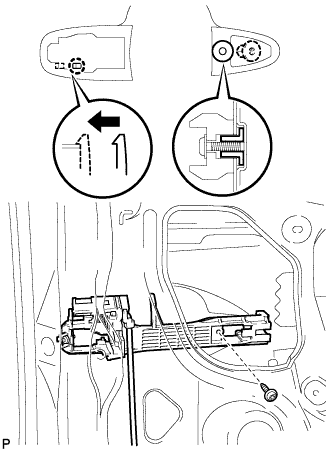
Loosen the bolt.
-
Connect the rod.
-
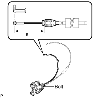
Adjust the cable as shown in the illustration.
Area Dimension a 50.5 mm (1.988 in.) -
Tighten the bolt.
- Torque:
- 5.7 N*m { 58 kgf*cm, 50 in.*lbf }
-
-
At the time of new article exchange
-
Using a T30 "TORX" socket wrench, install the slide door front lock assembly with the 4 screws.
- Torque:
- 5.5 N*m { 56 kgf*cm, 49 in.*lbf }
-
Connect the rod.
-
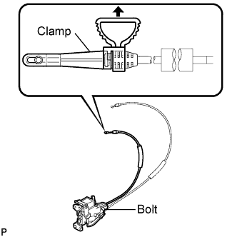
Tighten the bolt.
- Torque:
- 5.7 N*m { 58 kgf*cm, 50 in.*lbf }
-
Remove the clamp.
-
-
-
INSTALL REAR DOOR WINDOW GUIDE SUB-ASSEMBLY
-
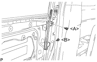
Install the rear door window guide sub-assembly with the 2 bolts.
- Torque:
- Bolt <A>
- 7.5 N*m { 77 kgf*cm, 66 in.*lbf }
- Bolt <B>
- 5.5 N*m { 56 kgf*cm, 49 in.*lbf }
-
-
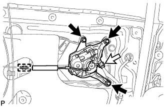
INSTALL REAR POWER WINDOW REGULATOR MOTOR ASSEMBLY
Note
The regulator arm must be below the intermediate position when installing the rear power window regulator motor assembly.
-
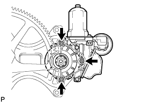
Using a T25 "TORX" socket wrench, install the rear power window regulator motor assembly with the 3 screws.
- Torque:
- 5.4 N*m { 55 kgf*cm, 48 in.*lbf }
Tech Tips
A new rear power window regulator motor assembly uses self-tapping screws to thread new installation holes when the self-tapping screws are inserted.
-
-
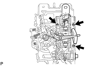
INSTALL REAR DOOR POWER WINDOW REGULATOR ASSEMBLY
-
Apply MP grease to the sliding parts of the rear door power window regulator assembly.
-
Install the temporary bolt to the rear door power window regulator assembly.
-
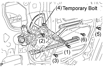
Temporarily install the rear door power window regulator assembly.
-
Tighten the 6 bolts in the order shown in the illustration to install the rear door power window regulator assembly.
- Torque:
- 7.5 N*m { 77 kgf*cm, 66 in.*lbf }
-
-
INSTALL REAR DOOR NO. 2 GLASS RUN
-
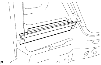
Install the rear door No. 2 glass run.
-
-
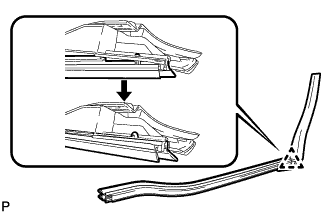
INSTALL REAR DOOR GLASS SUB-ASSEMBLY
-
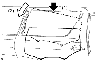
Insert the rear door glass sub-assembly into the door panel as indicated by the arrows, in the order shown in the illustration.
-
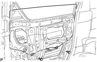
Install the rear door glass sub-assembly with the 2 bolts.
- Torque:
- 7.5 N*m { 77 kgf*cm, 66 in.*lbf }
-
-
INSTALL REAR DOOR GLASS RUN
-
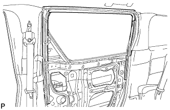
Install the rear door glass run.
-
-
INSTALL REAR DOOR BELT MOULDING
Tech Tips
Use the same procedure for the RH side and LH side Click here.
-
INSTALL REAR DOOR OUTSIDE MOULDING
Tech Tips
Use the same procedure for the RH side and LH side Click here.
-
INSTALL REAR DOOR WINDOW FRAME MOULDING
Tech Tips
Use the same procedure for the RH side and LH side Click here.
-
INSTALL SLIDE DOOR SERVICE HOLE COVER
-
Apply butyl tape to the slide door panel.
-
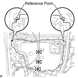
Attach a new slide door service hole cover according to the reference points on the slide door panel.
Note
Securely install the slide door service hole cover avoiding wrinkles and air bubbles.
-
Engage the 3 clamps.
-
-
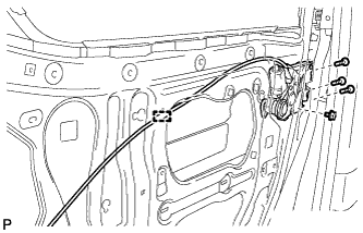
INSTALL REAR DOOR NO. 1 WIRE (w/o Power Slide Door)
-
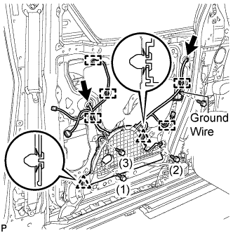
Engage the 2 clips and install the rear door No. 1 wire.
-
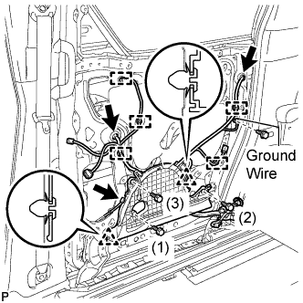
Tighten the 3 bolts in the order shown in the illustration to install the rear door No. 1 wire to the rear door panel.
Note
Be careful not to damage the wire while tightening the bolts.
-
Connect the ground wire with the bolt.
-
Connect each connector.
-
Engage the 5 clamps.
-
Engage the clip and secure the rear door No. 1 wire with the bolt.
-
Connect each connector.
-
-
INSTALL REAR DOOR NO. 1 WIRE (w/ Power Slide Door)
-
Engage the 2 clips and install the rear door No. 1 wire.
-
Tighten the 3 bolts in the order shown in the illustration to install the rear door No. 1 wire to the rear door panel.
Note
Be careful not to damage the wire while tightening the bolts.
-
Connect the ground wire with the bolt.
-
Connect each connector.
-
Engage the 5 clamps.
-
Engage the clip and secure the rear door No. 1 wire with the bolt.
-
Connect each connector.
-
Engage the clamp.
-
-
INSTALL REAR SIDE STEP SUPPORT
-
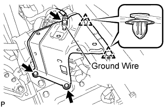
Engage the 2 clips and install the rear side step support .
-
Install the 2 bolts.
- Torque:
- 7.8 N*m { 80 kgf*cm, 69 in.*lbf }
-
Connect the ground wire with the bolt.
-
-
INSTALL SLIDE DOOR CLOSER RELAY (w/ Easy Closer)
-
Install the slide door closer relay with the 2 screws.
-
Connect the connector.
-
-
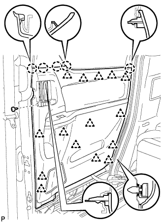
INSTALL REAR DOOR SCUFF PLATE
-
Captain type rear seat:
-
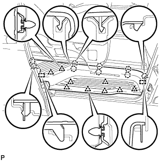
Engage the 2 guides, 9 clips and 9 claws to install the rear door scuff plate RH.
-
-
Tip-up type rear seat:
-
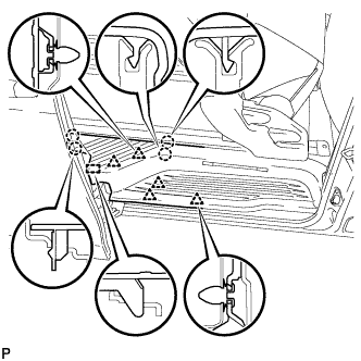
Using the reclining lever or foot-operated walk-in pedal, tip up the rear No. 1 seat and slide it to the foremost position.
-
Engage the 5 clips, 4 claws and guide on the rear side of the scuff plate as shown in the illustration.
-
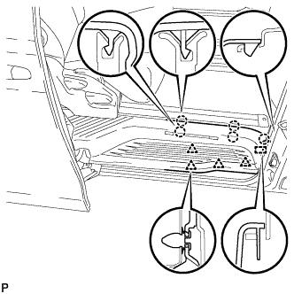
Using the slide lever, slide the rear No. 1 seat to the rearmost position.
-
Engage the 4 clips, 5 claws and guide on the front side of the scuff plate as shown in the illustration to install the rear door scuff plate RH.
-
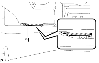
Text in Illustration *1 Protective Tape Remove the protective tape applied to the bottom of the rear seat.
-
-
-
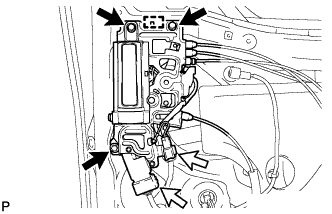
INSTALL DOOR SIDE AIRBAG SENSOR
-
Check that the engine switch is off.
-
Check that the cable is disconnected from the negative (-) battery terminal.
CAUTION:
Wait at least 90 seconds after disconnecting the cable from the negative (-) battery terminal to disable the SRS system.
-
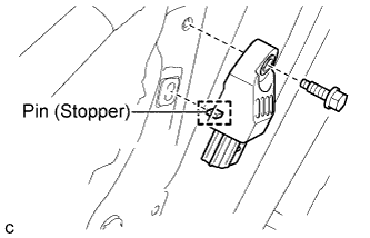
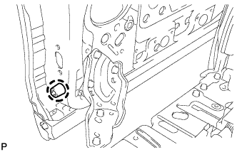
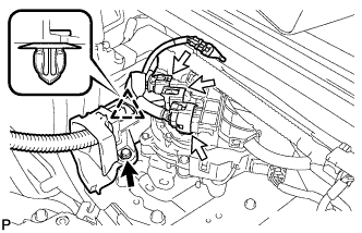
Insert the pin (stopper) into the body hole and install the door side airbag sensor to the slide door with the bolt.
- Torque:
- 9.0 N*m { 92 kgf*cm, 80 in.*lbf }
Note
-
If the door side airbag sensor has been dropped, or there are any cracks, dents or other defects in the case or connector, replace it with a new one.
-
When installing the door side airbag sensor, be careful that the SRS wiring does not interfere with or is not pinched between other parts.
-
Make sure that the pin (stopper) is securely inserted into the body hole.
-
Tighten the bolt while holding the door side airbag sensor because the door side airbag sensor pin (stopper) is easily damaged.
-
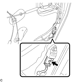
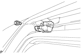
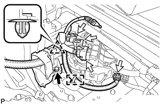
Connect the connector to the door side airbag sensor.
Note
When connecting the airbag connector, take care not to damage the airbag wire harness.
-
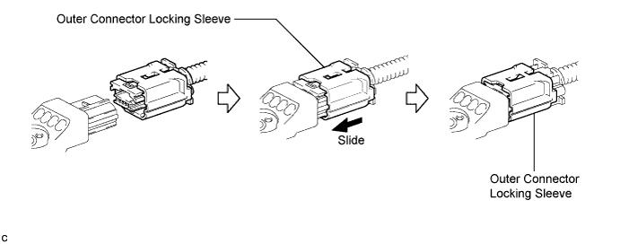
Connect the connector as shown in the illustration (When locking, make sure that the outer connector locking sleeve returns to its original position and a click sound can be heard).
Tech Tips
When connected, the outer connector locking sleeve will slide. Be sure not to hold the outer connector locking sleeve while connecting, as it may result in an insecure fit.
-
-
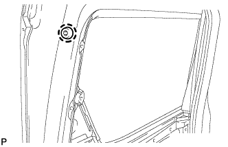
Check that there is no looseness in the installation parts of the door side airbag sensor.
-
-
INSTALL NO. 1 WITH BOX SPEAKER ASSEMBLY
-
Engage the clamp and install the No. 1 with box speaker assembly with the 3 bolts.
-
Connect the connector.
-
-
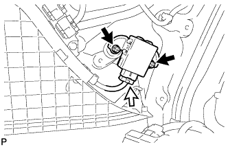
INSTALL SLIDE DOOR LOCK RELEASE MOTOR ASSEMBLY (w/ Power Slide Door)
-
Install the slide door lock release motor assembly with the 3 screws.
-
Connect the connector.
-
Engage the clamp.
-
-
INSTALL REAR DOOR INSIDE HANDLE SUB-ASSEMBLY
-
Install the rear door inside handle sub-assembly with the 3 screws.
-
Connect each rod.
-
-
INSTALL SLIDE DOOR LOCK REMOTE CONTROL SUB-ASSEMBLY (w/o Power Slide Door)
-
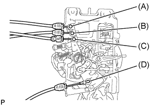
Connect each cable to the slide door lock remote control sub-assembly.
Tech Tips
Refer to the following table for the connection position of each cable:
Position Cable to be connected (A) Front lock cable (B) Rear lock cable (C) Full open stop lock cable (D) Outside handle cable -
Engage the guide and install the slide door lock remote control sub-assembly.
-
Install the 3 bolts.
- Torque:
- 7.5 N*m { 77 kgf*cm, 66 in.*lbf }
-
Connect each connector.
-
-
INSTALL SLIDE DOOR LOCK REMOTE CONTROL SUB-ASSEMBLY (w/ Power Slide Door)
-
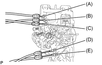
Connect each cable to the slide door lock remote control sub-assembly.
Tech Tips
Refer to the following table for the connection position of each cable:
Position Cable to be connected (A) Front lock cable (B) Rear lock cable (C) Full open stop lock cable (D) Outside handle cable (E) Release motor cable -
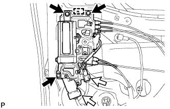
Engage the guide and install the slide door lock remote control sub-assembly.
-
Install the 3 bolts.
- Torque:
- 7.5 N*m { 77 kgf*cm, 66 in.*lbf }
-
Connect each connector.
-
-
INSTALL SLIDE DOOR DOWN FEMALE STOPPER
-
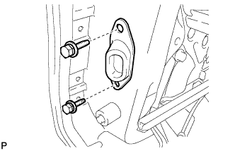
Install the slide door down female stop with the 2 bolts.
- Torque:
- 7.5 N*m { 77 kgf*cm, 66 in.*lbf }
-
-
INSTALL REAR DOOR REAR GUIDE BRACKET GARNISH
-
Engage the clip to install the rear door rear guide bracket garnish to the rear door glass weatherstrip inner.
-
-
INSTALL REAR DOOR GLASS WEATHERSTRIP INNER WITH GARNISH
-
Engage the claw to install the rear door glass weatherstrip inner with garnish.
-
-
INSTALL REAR DOOR FRONT WINDOW GUIDE
-
Engage the clip.
-
Install the rear door front window guide with the screw.
-
-
INSTALL SLIDE DOOR WINDOW GARNISH (w/o Navigation System for HDD)
-
Engage the 5 clips to install the slide door window garnish.
-
-
INSTALL REAR NO. 3 SPEAKER ASSEMBLY (w/ Navigation System for HDD)
-
Engage the 3 claws and install the rear No. 3 speaker assembly as shown in the illustration.
-
Engage the clamp.
-
-
INSTALL SLIDE DOOR WINDOW GARNISH (w/ Navigation System for HDD)
-
Engage the 5 clips to install the slide door window garnish.
-
Connect the connector.
-
-
INSTALL REAR POWER WINDOW REGULATOR SWITCH ASSEMBLY
-
Engage the 2 claws to install the rear power window regulator switch assembly.
-
-
INSPECT REAR DOOR PANEL SUB-ASSEMBLY
Tech Tips
Use the same procedure for the RH side and LH side Click here.
-
ADJUST SLIDE DOOR
Tech Tips
Use the same procedure for the RH side and LH side Click here.
-
INSTALL REAR DOOR TRIM BOARD SUB-ASSEMBLY
-
Connect the connector.
-
Engage the 15 clips and 5 claws to install the rear door trim board to the slide door panel.
-
Using a T25 "TORX" socket wrench, install the screw.
-
-
CONNECT CABLE TO NEGATIVE BATTERY TERMINAL
Note
When disconnecting the cable, some systems need to be initialized after the cable is reconnected Click here.
-
PERFORM DIAGNOSTIC SYSTEM CHECK
-
INSPECT SRS WARNING LIGHT
-
INITIALIZE POWER WINDOW CONTROL SYSTEM