FRONT SEAT OUTER BELT ASSEMBLY INSTALLATION

-
INSTALL FRONT SHOULDER BELT ANCHOR ADJUSTER ASSEMBLY
-
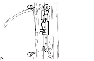
Engage the adjuster positioning hole with the claw and install the front shoulder belt anchor adjuster assembly with the 2 bolts.
- Torque:
- 42 N*m { 428 kgf*cm, 31 ft.*lbf }
-
-
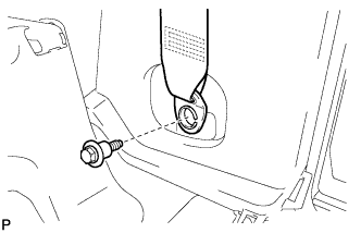
INSTALL FRONT SEAT OUTER BELT ASSEMBLY
-
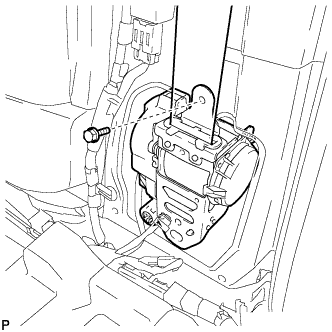
Install the front seat outer belt assembly with the bolt.
- Torque:
- 8.5 N*m { 87 kgf*cm, 75 in.*lbf }
-
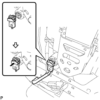
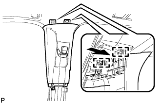
Connect the connector and lock the locking button as shown in the illustration.
Note
Securely lock the locking button.
-
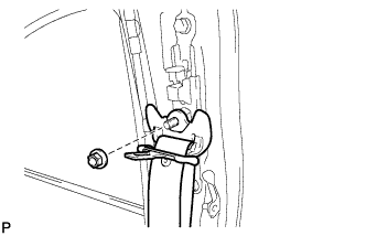
Connect the shoulder anchor of the front seat outer belt assembly with the nut.
- Torque:
- 42 N*m { 428 kgf*cm, 31 ft.*lbf }
-
-
INSTALL UPPER CENTER PILLAR GARNISH
-
Engage the 2 guides.
-
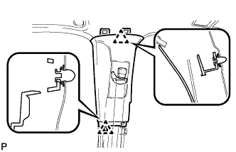
Engage the 2 clips to install the upper center pillar garnish RH.
-
-
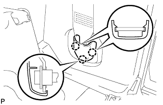
INSTALL LOWER CENTER PILLAR GARNISH
-
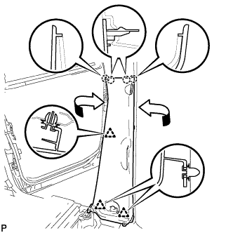
Engage the 4 claws and 3 clips to install the lower center pillar garnish RH as shown in the illustration.
-
-
INSTALL NO. 2 ASSIST GRIP
-
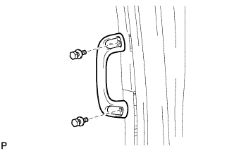
Install the No. 2 assist grip with the 2 bolts.
-
-
INSTALL ASSIST GRIP PLUG
-
Engage the 4 claws to install the 2 assist grip plugs.
-
-
CONNECT FRONT SEAT OUTER BELT ASSEMBLY
-
Install the floor end of the front seat outer belt assembly with the bolt.
- Torque:
- 42 N*m { 428 kgf*cm, 31 ft.*lbf }
-
Check if the ELR locks.
Note
The check should be performed with the outer belt assembly installed.
-
With the belt assembly installed, check that the belt locks when it is pulled out quickly.
-
-
-
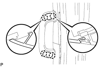
INSTALL LAP BELT OUTER ANCHOR COVER
-
Engage the 3 claws to install the lap belt outer anchor cover.
-
-
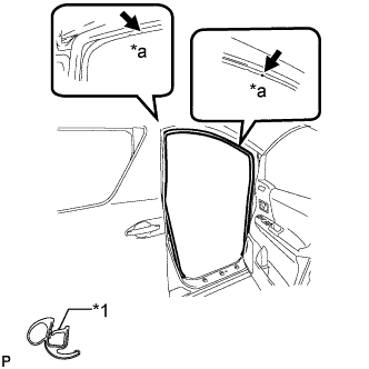
INSTALL NO. 1 SLIDE DOOR WEATHERSTRIP
-
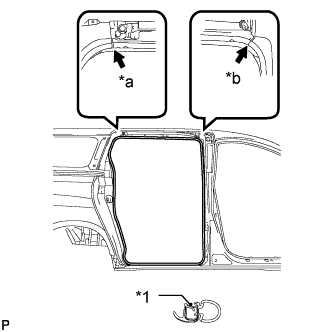
Text in Illustration *1 Alignment Mark *a Pink *b White Align the alignment marks on the weatherstrip with the protruding portions on the body indicated by the arrows in the illustration, and install the No. 1 slide door weatherstrip RH.
Note
After installation, check that the corners fit correctly.
-
-
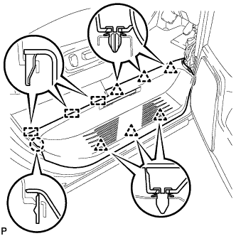
INSTALL REAR DOOR SCUFF PLATE
-
Captain type rear seat:
-
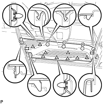
Engage the 2 guides, 9 clips and 9 claws to install the rear door scuff plate RH.
-
-
Tip-up type rear seat:
-
Using the reclining lever or foot-operated walk-in pedal, tip up the rear No. 1 seat and slide it to the foremost position.
-
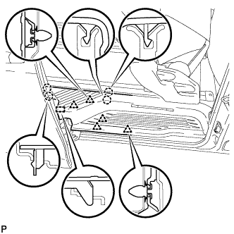
Engage the 5 clips, 4 claws and guide on the rear side of the scuff plate as shown in the illustration.
-
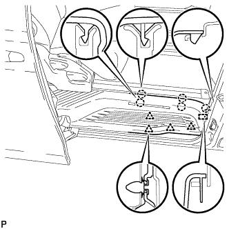
Using the slide lever, slide the rear No. 1 seat to the rearmost position.
-
Engage the 4 clips, 5 claws and guide on the front side of the scuff plate as shown in the illustration to install the rear door scuff plate RH.
-
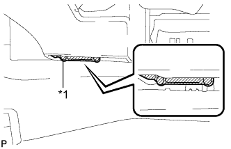
Text in Illustration *1 Protective Tape Remove the protective tape applied to the bottom of the rear seat.
-
-
-
INSTALL FRONT DOOR OPENING TRIM WEATHERSTRIP
-
Text in Illustration *1 Alignment Mark *a White Align the alignment marks on the weatherstrip with the protruding portions on the body indicated by the arrows in the illustration, and install the front door opening trim weatherstrip RH.
Note
After installation, check that the corners fit correctly.
-
-
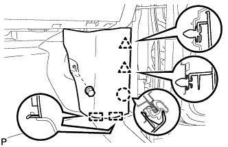
INSTALL FRONT DOOR SCUFF PLATE
-
Engage the 3 guides, claw and 6 clips to install the door scuff plate assembly RH.
-
-
INSTALL COWL SIDE TRIM BOARD (for RHD)
-

Engage the 2 guides, claw and clip to install the cowl side trim board RH.
-
Install the clip(A).
-
-
INSTALL COWL SIDE TRIM BOARD (for LHD)
-
Engage the 2 guides, claw and the 2 clips to install the cowl side trim board RH.
-
Install the clip(A).
-
-
CONNECT CABLE TO NEGATIVE BATTERY TERMINAL
Note
When disconnecting the cable, some systems need to be initialized after the cable is reconnected Click here.
-
INSPECT SRS WARNING LIGHT
-
Inspect the SRS warning light Click here.
-