-
Use the same procedure for the RH side and LH side.
-
The following procedure is for the RH side.
- Click here
PRECAUTION
CAUTION:Be sure to read Precaution thoroughly before servicing (Click here).
- Click here
DISCONNECT CABLE FROM NEGATIVE BATTERY TERMINAL
CAUTION:Wait at least 90 seconds after disconnecting the cable from the negative (-) battery terminal to disable the SRS system.
Note:When disconnecting the cable, some systems need to be initialized after the cable is reconnected (Click here).
- Click here
REMOVE COWL SIDE TRIM BOARD
-

Remove the clip.
-
Disengage the clip, claw and 2 guides, and remove the cowl side trim board RH.
-
- Click here
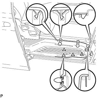
REMOVE FRONT DOOR SCUFF PLATE
-
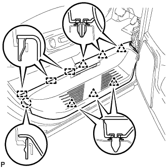
Disengage the claw, 6 clips and 3 guides, and remove the door scuff plate assembly RH.
-
- Click here
REMOVE FRONT DOOR OPENING TRIM WEATHERSTRIP
-
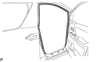
Remove the front door opening trim weatherstrip RH.
-
- Click here
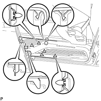
REMOVE REAR DOOR SCUFF PLATE
-
Captain type rear seat:
-
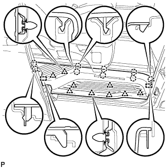
Disengage the 9 claws, 9 clips and 2 guides, and remove the rear door scuff plate RH.
-
-
Tip-up type rear seat:
-
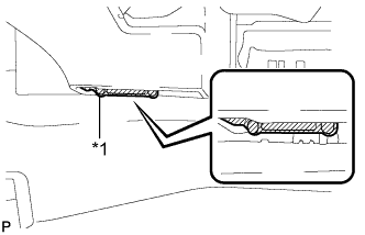
Apply protective tape to the bottom of the seat as shown in the illustration.
Table 1. Text in Illustration *1 Protective Tape -
Using the slide lever, slide the rear No. 1 seat to the rearmost position.
-
Disengage the 4 clips, 5 claws and guide on the front side of the scuff plate as shown in the illustration.
Note:To prevent damage to the scuff plate, make sure not to use excessive force when disengaging the clips, claws and guide.
-
Using the reclining lever or foot-operated walk-in pedal, tip up the rear No. 1 seat and slide it to the foremost position.
-
Disengage the 5 clips, 4 claws and guide on the rear side of the scuff plate as shown in the illustration, and remove the rear door scuff plate RH.
Note:To prevent damage to the scuff plate, make sure not to use excessive force when disengaging the clips, claws and guide.
-
-
- Click here
DISCONNECT NO. 1 SLIDE DOOR WEATHERSTRIP
- Click here
REMOVE LAP BELT OUTER ANCHOR COVER
-
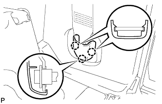
Disengage the 3 claws to remove the lap belt outer anchor cover.
-
- Click here
DISCONNECT FRONT SEAT OUTER BELT ASSEMBLY
-
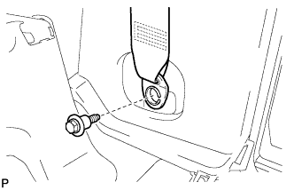
Remove the bolt and disconnect the floor end of the front seat outer belt assembly.
-
- Click here
REMOVE ASSIST GRIP PLUG
-
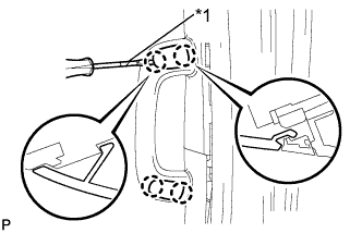
Using a screwdriver, disengage the 4 claws and remove the 2 assist grip plugs.
Table 2. Text in Illustration *1 Protective Tape Tip:Tape the screwdriver tip before use.
-
- Click here
REMOVE NO. 2 ASSIST GRIP
-
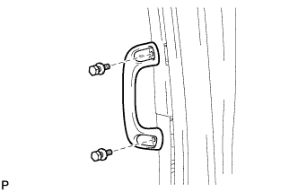
Remove the 2 bolts and the No. 2 assist grip.
-
- Click here
REMOVE LOWER CENTER PILLAR GARNISH
-
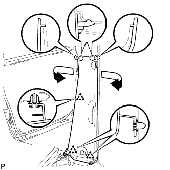
Disengage the 4 claws and 3 clips, and remove the lower center pillar garnish RH.
-
- Click here
REMOVE SIDE AIRBAG SENSOR ASSEMBLY
-
Check that the engine switch is off.
-
Check that the cable is disconnected from the negative (-) battery terminal.
CAUTION:Wait at least 90 seconds after disconnecting the cable from the negative (-) battery terminal to disable the SRS system.
-
Disconnect the connector from the side airbag sensor assembly.
Note:When disconnecting any airbag connector, take care not to damage the airbag wire harness.
-
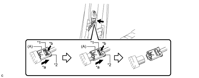
Push down the white housing lock and slide the yellow CPA. (At this time, the connector cannot be disconnected yet.)
Table 3. Text in Illustration *1 White Housing Lock *2 Yellow CPA *a Slide *b Push -
Push down the white housing lock again and disconnect the connector.
Note:Do not push down the part (A) shown in the illustration when disconnecting the connector.
-
-
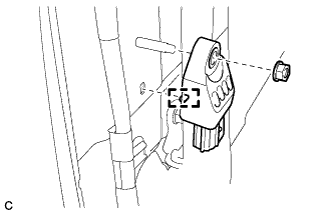
Remove the nut and side airbag sensor assembly from the vehicle body.
Note:Loosen the nut while holding the side airbag sensor assembly because the side airbag sensor assembly pin (stopper) is easily damaged.
-
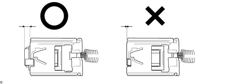
After disconnecting the connector, check that the position of the white housing lock is correct as shown in the illustration.
-