ELECTRICAL KEY OSCILLATOR (for Front Door) REMOVAL

-
PRECAUTION
Note
After turning the engine switch off, waiting time may be required before disconnecting the cable from the negative (-) battery terminal. Therefore, make sure to read the disconnecting the cable from the negative (-) battery terminal notices before proceeding with work Click here.
-
DISCONNECT CABLE FROM NEGATIVE BATTERY TERMINAL
Note
When disconnecting the cable, some systems need to be initialized after the cable is reconnected Click here.
-
REMOVE FRONT DOOR LOWER FRAME BRACKET GARNISH
-
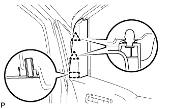
Disengage the 2 clips and guide, and remove the front door lower frame bracket garnish.
-
-
REMOVE LOWER DOOR FRAME GARNISH
-
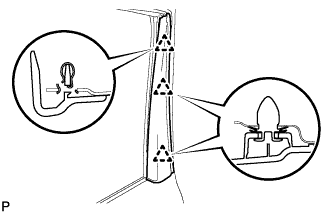
Disengage the 3 clips and remove the lower door frame garnish.
-
-
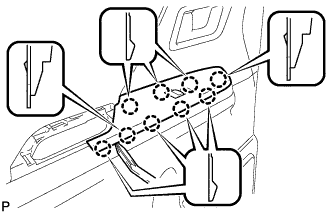
REMOVE FRONT DOOR INSIDE HANDLE BEZEL PLUG
-
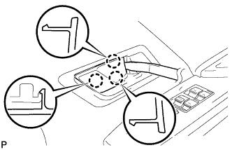
Using a moulding remover, disengage the 3 claws, and remove the front door inside handle bezel plug.
-
-
REMOVE COURTESY LIGHT ASSEMBLY
-
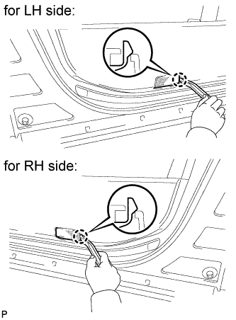
Using a moulding remover, disengage the claw.
-
Disconnect the connector and remove the courtesy light assembly.
-
-
REMOVE FRONT DOOR PULL HANDLE
-
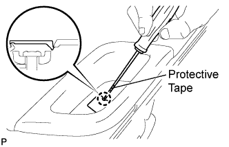
Using a screwdriver with the tip wrapped with protective tape, disengage the claw and open the cover.
-
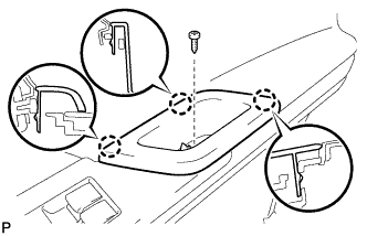
Remove the screw.
-
Disengage the 3 claws and remove the front door pull handle.
-
-
REMOVE POWER WINDOW REGULATOR MASTER SWITCH ASSEMBLY WITH FRONT DOOR ARMREST BASE PANEL (for Driver Side)
-
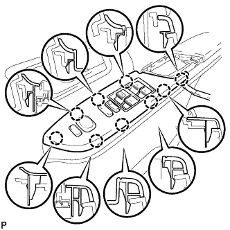
Using a moulding remover, disengage the 9 claws and remove the power window regulator master switch assembly with front door armrest base panel.
-
Disconnect the connector.
-
-
REMOVE POWER WINDOW REGULATOR SWITCH ASSEMBLY WITH FRONT DOOR ARMREST BASE PANEL (for Front Passenger Side)
-
Using a moulding remover, disengage the 9 claws.
-
Disconnect the connector and remove the power window regulator switch assembly with front door armrest base panel.
-
-
REMOVE FRONT DOOR TRIM BOARD SUB-ASSEMBLY
-
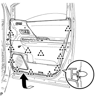
Remove the 2 screws.
-
Using a clip remover, disengage the 12 clips.
-
Pull out the front door trim board in the direction indicated by the arrow shown in the illustration.
-
Raise the front door trim board and remove the front door trim board together with the front door inner glass weatherstrip.
-
for Driver Side with Memory:
-
Disconnect the connector.
-
-
Disengage the 2 claws and disconnect the front door inside handle sub-assembly.
-
-
REMOVE OUTER MIRROR CONTROL ECU ASSEMBLY (for Driver Side)
-
Disconnect the 2 connectors.
-
Remove the 2 screws and the outer mirror control ECU assembly.
-
-
REMOVE DOOR TRIM BRACKET
-
Disengage the clamp.
-
Remove the 2 screws and door trim bracket.
-
-
REMOVE FRONT DOOR SERVICE HOLE COVER
-
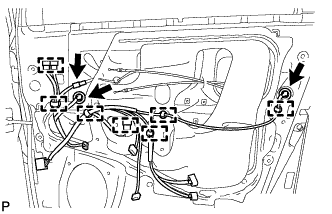
Disconnect each connector and the 7 clamps.
-
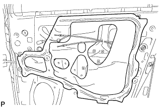
Remove the front door service hole cover.
Tech Tips
Remove the remaining butyl tape on the door.
-
-
REMOVE FRONT DOOR OUTSIDE HANDLE COVER WITH LOCK CYLINDER ASSEMBLY (for Driver Side)
-
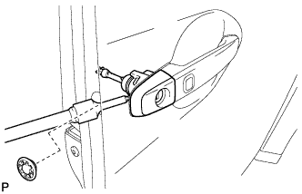
Remove the hole plug.
-
Using a T30 "TORX" socket wrench, loosen the screw and remove the front door outside handle cover with lock cylinder assembly.
Tech Tips
The screw cannot be removed because it is integrated into the front door outside handle frame sub-assembly.
-
-
REMOVE FRONT DOOR OUTSIDE HANDLE COVER (for Front Passenger Side)
-
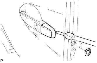
Remove the hole plug.
-
Using a T30 "TORX" socket wrench, loosen the screw and remove the front door outside handle cover.
Tech Tips
The screw cannot be removed because it is integrated into the front door outside handle frame sub-assembly.
-
-
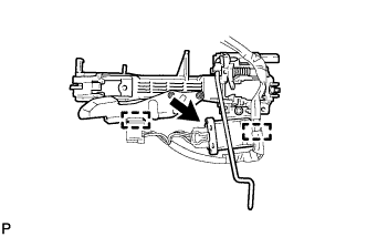
REMOVE FRONT DOOR OUTSIDE HANDLE ASSEMBLY
-
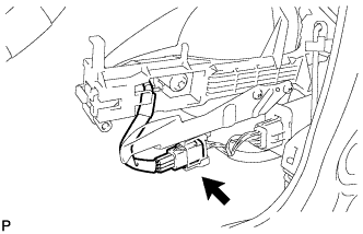
Disconnect the connector.
-
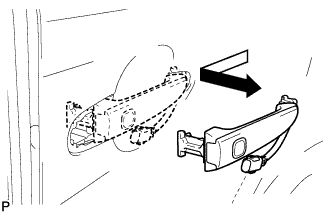
Remove the front door outside handle assembly as shown in the illustration.
-
-
REMOVE FRONT DOOR FRONT OUTSIDE HANDLE PAD
-
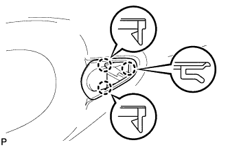
Disengage the 3 claws and remove the front door front outside handle pad.
-
-
REMOVE FRONT DOOR REAR OUTSIDE HANDLE PAD
-
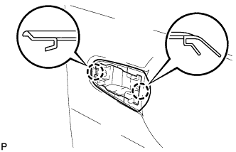
Disengage the 2 claws and remove the front door rear outside handle pad.
-
-
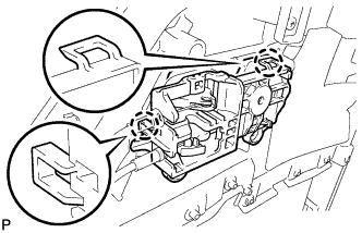
REMOVE FRONT DOOR LOCK ASSEMBLY
-
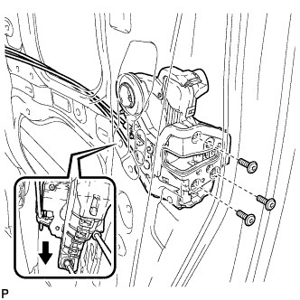
Using a T30 "TORX" socket wrench, remove the 3 screws.
-
Slide the front door lock assembly downward, and remove the front door lock assembly and cables as a unit.
-
Remove the door lock wiring harness seal from the front door lock assembly.
-
-
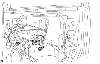
REMOVE FRONT DOOR OUTSIDE HANDLE FRAME SUB-ASSEMBLY
-
Disengage the clamp.
-
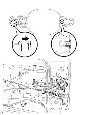
Using a T30 "TORX" socket wrench, remove the screw.
-
Disengage the claw and remove the front door outside handle frame sub-assembly.
-
Disconnect the connector.
-
Disengage the 2 clamps.
-
-
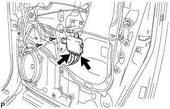
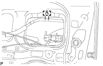
REMOVE DOOR ELECTRICAL KEY OSCILLATOR
-
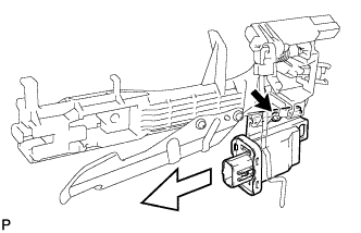
Remove the screw and door electrical key oscillator.
-