SLIDE DOOR LOCK INSTALLATION

-
INSTALL REAR DOOR LOCK ASSEMBLY
-
Apply MP grease to the sliding parts of the rear door lock assembly.
-
Using a T30 "TORX" socket wrench, install the rear door lock assembly with the 3 screws.
- Torque:
- 8.0 N*m { 82 kgf*cm, 71 in.*lbf }
-
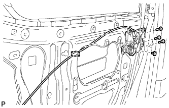
Install the bolt.
- Torque:
- 8.0 N*m { 82 kgf*cm, 71 in.*lbf }
-
Engage the clamp.
-
-
INSTALL SLIDE DOOR FRONT LOCK ASSEMBLY
-
Apply MP grease to the sliding parts of the slide door front lock assembly.
-
At the time of reuse.
-
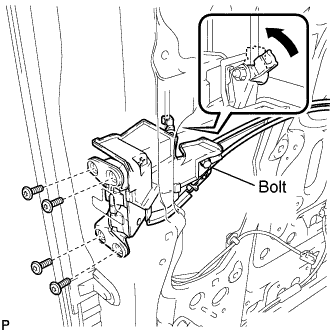
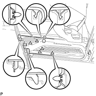
Using a T30 "TORX" socket wrench, install the slide door front lock assembly with the 4 screws.
- Torque:
- 5.5 N*m { 56 kgf*cm, 49 in.*lbf }
-
Loosen the bolt.
-
Connect the rod.
-
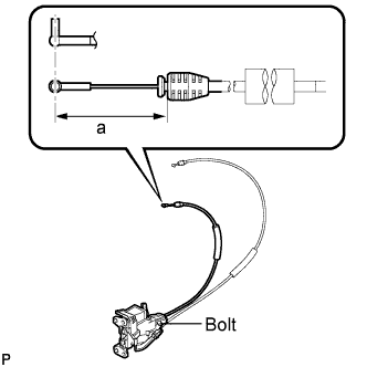
Adjust the cable as shown in the illustration.
Area Dimension a 50.5 mm (1.988 in.) -
Tighten the bolt.
- Torque:
- 5.7 N*m { 58 kgf*cm, 50 in.*lbf }
-
-
At the time of new article exchange.
-
Using a T30 "TORX" socket wrench, install the slide door front lock assembly with the 4 screws.
- Torque:
- 5.5 N*m { 56 kgf*cm, 49 in.*lbf }
-
Connect the rod.
-
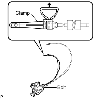
Tighten the bolt.
- Torque:
- 5.7 N*m { 58 kgf*cm, 50 in.*lbf }
-
Remove the clamp.
-
-
-
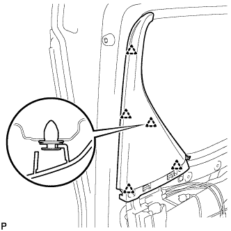
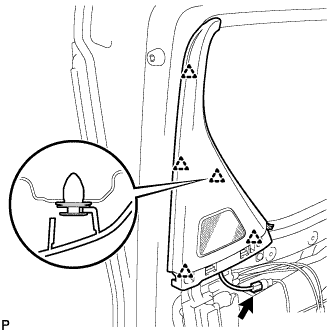
INSTALL REAR DOOR WINDOW GUIDE SUB-ASSEMBLY
-
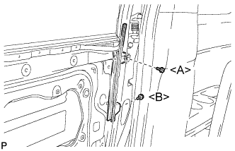
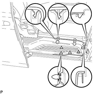
Install the rear door window guide sub-assembly with the 2 bolts.
- Torque:
- Bolt <A>
- 7.5 N*m { 77 kgf*cm, 66 in.*lbf }
- Bolt <B>
- 5.5 N*m { 56 kgf*cm, 49 in.*lbf }
-
-
INSTALL SLIDE DOOR SERVICE HOLE COVER
-
Apply butyl tape to the slide door panel.
-
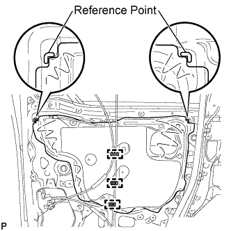
Attach a new slide door service hole cover according to the reference points on the slide door panel.
Note
Securely install the slide door service hole cover avoiding wrinkles and air bubbles.
-
Engage the 3 clamps.
-
-
INSTALL REAR DOOR NO. 1 WIRE
w/o Power Slide Door: Click here
w/ Power Slide Door: Click here
-
INSTALL SIDE STEP SUPPORT REAR
-
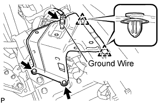
Engage the 2 clips and install the rear side step support .
-
Install the 2 bolts.
- Torque:
- 7.8 N*m { 80 kgf*cm, 69 in.*lbf }
-
Connect the ground wire with the bolt.
-
-
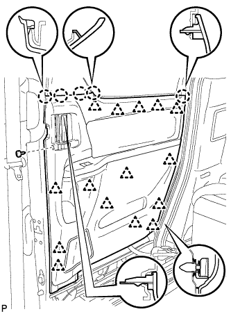
INSTALL REAR DOOR SCUFF PLATE
-
Captain type rear seat:
-
Engage the 2 guides, 9 clips and 9 claws to install the rear door scuff plate RH.
-
-
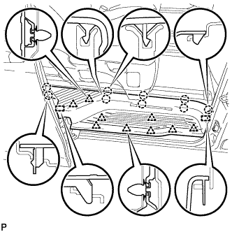
Tip-up type rear seat:
-
Using the reclining lever or foot-operated walk-in pedal, tip up the rear No. 1 seat and slide it to the foremost position.
-
Engage the 5 clips, 4 claws and guide on the rear side of the scuff plate as shown in the illustration.
-
Using the slide lever, slide the rear No. 1 seat to the rearmost position.
-
Engage the 4 clips, 5 claws and guide on the front side of the scuff plate as shown in the illustration to install the rear door scuff plate RH.
-
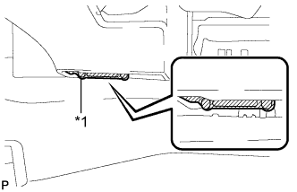
Text in Illustration *1 Protective Tape Remove the protective tape applied to the bottom of the rear seat.
-
-
-
INSTALL SLIDE DOOR LOCK RELEASE MOTOR ASSEMBLY (w/ Power Slide Door)
-
Install the slide door lock release motor assembly with the 3 screws.
-
Connect the connector.
-
Engage the clamp.
-
-
INSTALL REAR DOOR LOCK ACTUATOR ASSEMBLY
-
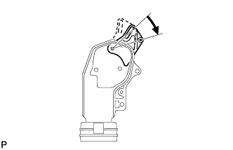
Move the motor lever of the rear door lock actuator assembly to the unlock position as shown in the illustration.
-
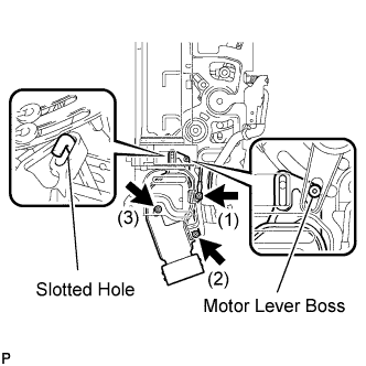
As shown in the illustration, pass the rod of the slide door inside handle sub-assembly through the slotted hole of the rear door lock actuator assembly.
-
As shown in the illustration, install the motor lever boss of the rear door lock actuator assembly to the slide door inside handle sub-assembly.
-
As shown in the illustration, pass the rod of the slide door inside handle sub-assembly through the slotted hole of the rear door lock actuator assembly RH.
-
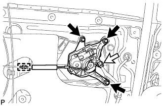
Install the 3 screws in the order shown in the illustration to install the rear door lock actuator assembly.
Note
-
Move the motor lever of the rear door lock actuator assembly to the lock and unlock positions to make sure that the lever moves smoothly and is not stuck.
-
If the lever does not move smoothly, slightly loosen the screws and adjust the position of the rear door lock actuator assembly by sliding it back and forth.
Tech Tips
For the slide door lock remote control sub-assembly with the earth wire, install the earth wire with the screw (1).
-
-
-
INSTALL SLIDE DOOR LOCK REMOTE CONTROL SUB-ASSEMBLY
w/o Power Slide Door: Click here
w/ Power Slide Door: Click here
-
INSTALL REAR DOOR GLASS WEATHERSTRIP INNER WITH GARNISH
-
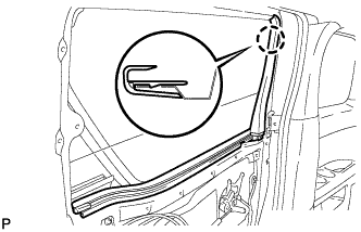
Engage the claw to install the rear door glass weatherstrip inner with garnish.
-
-
INSTALL REAR DOOR FRONT WINDOW GUIDE
-
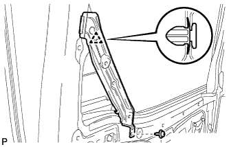
Engage the clip.
-
Install the rear door front window guide with the screw.
-
-
INSTALL SLIDE DOOR WINDOW GARNISH (w/o Navigation System for HDD)
-
Engage the 5 clips to install the slide door window garnish.
-
-
INSTALL SLIDE DOOR WINDOW GARNISH (w/ Navigation System for HDD)
-
Engage the 5 clips to install the slide door window garnish.
-
Connect the connector.
-
-
INSTALL REAR DOOR TRIM BOARD SUB-ASSEMBLY
-
Connect the connector.
-
Engage the 15 clips and 5 claws to install the rear door trim board to the slide door panel.
-
Using a T25 "TORX" socket wrench, install the screw.
-
-
CONNECT CABLE TO NEGATIVE BATTERY TERMINAL
Note
When disconnecting the cable, some systems need to be initialized after the cable is reconnected Click here.