FRONT DOOR LOCK INSTALLATION

-
INSTALL FRONT DOOR LOCK ASSEMBLY
Note
-
When reusing the removed front door lock assembly, replace the door lock wiring harness seal on the connector with a new one.
-
Do not allow grease or dust to adhere to the door lock wiring harness seal surface of the connector.
-
Reusing the door lock wiring harness seal or using a damaged door lock wiring harness seal may cause water intrusion to the connection. This may result in a malfunction of the front door lock assembly.
-
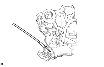
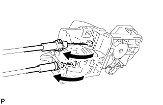
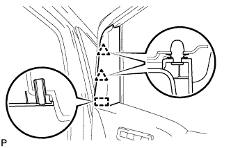
Install the front door inside locking cable assembly.
-
Engage the 3 claws.
-
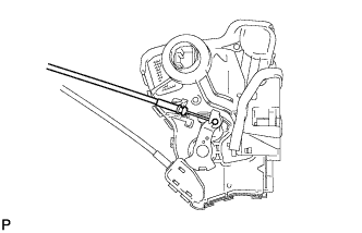
Install the front door lock remote control cable assembly.
-
Apply MP grease to the sliding parts of the front door lock assembly.
-
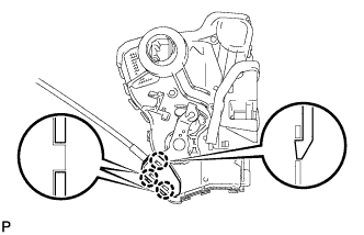
Install a new door lock wiring harness seal to the front door lock assembly.
-
Insert the front door lock open rod to the front door lock assembly.
-
Make sure that the front door lock open rod is securely connected to the front door lock assembly.
-
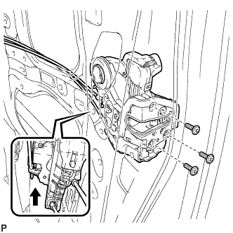
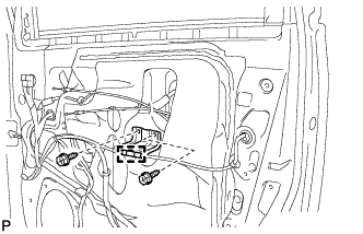
Using a T30 "TORX" socket wrench, install the front door lock assembly with the 3 screws.
- Torque:
- 5.5 N*m { 56 kgf*cm, 49 in.*lbf }
-
-
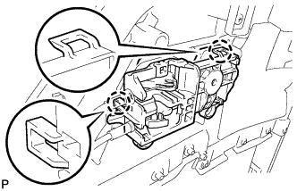
INSTALL FRONT DOOR OUTSIDE HANDLE COVER WITH LOCK CYLINDER ASSEMBLY (for Driver Side)
-
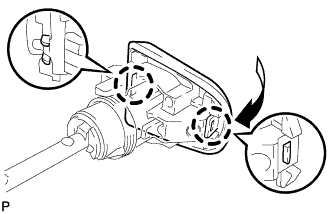
Engage the 2 claws to install the front door outside handle cover to the front door lock cylinder.
-
-
INSTALL FRONT DOOR REAR LOWER FRAME SUB-ASSEMBLY
-
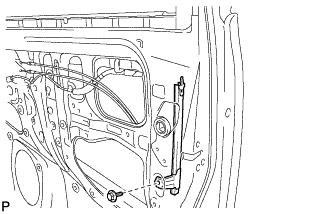
Install the front door rear lower frame sub-assembly with the bolt.
- Torque:
- 7.5 N*m { 77 kgf*cm, 66 in.*lbf }
-
-
INSTALL FRONT DOOR SERVICE HOLE COVER
-
Apply butyl tape to the front door panel.
-
Pass the front door lock remote control cable and front door inside the locking cable through a new front door service hole cover.
-
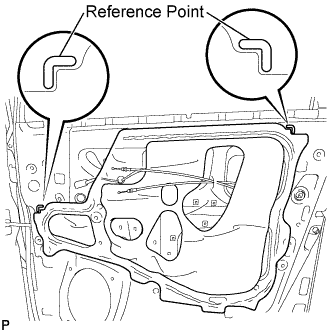
Attach the front door service hole cover according to the reference points on the front door panel.
Note
Securely install the front door service hole cover avoiding wrinkles and air bubbles.
-
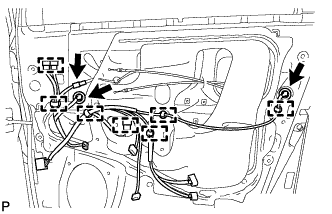
Connect each connector.
-
Engage the 7 clamps.
-
-
INSTALL DOOR TRIM BRACKET
-
Install the door trim bracket with the 2 screws.
-
Engage the clamp to the door trim bracket.
-
-
INSTALL OUTER MIRROR CONTROL ECU ASSEMBLY (for Driver Side)
-
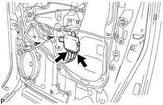
Install the outer mirror control ECU assembly with the 2 screws.
-
Connect the 2 connectors.
-
-
INSTALL FRONT DOOR INSIDE HANDLE SUB-ASSEMBLY
-
Connect the front door lock remote control cable and front door inside locking cable to the front door inside handle sub-assembly.
-
Engage the 2 claws to install the front door inside handle sub-assembly.
-
-
INSTALL FRONT DOOR TRIM BOARD SUB-ASSEMBLY
-
for Driver Side with Memory:
-
Connect the connector.
-
-
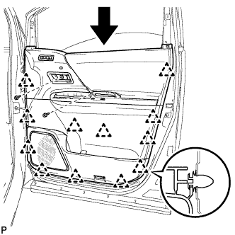
Engage the 12 clips and install the front door trim board sub-assembly to the front door panel.
-
Install the 2 screws.
-
-
INSTALL POWER WINDOW REGULATOR MASTER SWITCH ASSEMBLY WITH FRONT DOOR ARMREST BASE PANEL (for Driver Side)
-
Connect the connector.
-
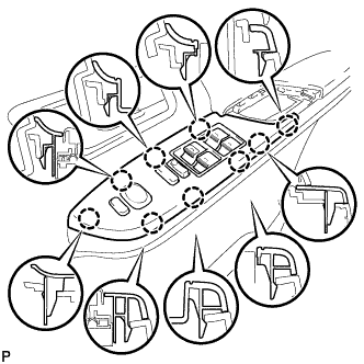
Engage the 9 claws to install the power window regulator master switch assembly with front door armrest base panel.
-
-
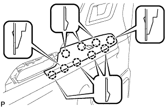
INSTALL POWER WINDOW REGULATOR SWITCH ASSEMBLY WITH FRONT DOOR ARMREST BASE PANEL (for Front Passenger Side)
-
Connect the connector.
-
Engage the 9 claws to install the power window regulator switch assembly with front door armrest base panel.
-
-
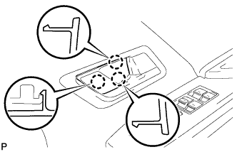
INSTALL FRONT DOOR PULL HANDLE
-
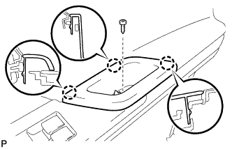
Engage the 3 claws.
-
Install the front door pull handle with the screw.
-
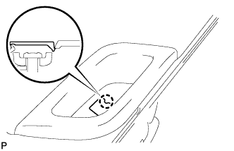
Engage the claw and close the cover.
-
-
INSTALL REFLEX REFLECTOR (w/o Courtesy Light)
-
Connect the connector.
-

Engage the claw to install the reflex reflector.
-
-
INSTALL COURTESY LIGHT ASSEMBLY (w/ Courtesy Light)
-
Connect the connector.
-
Engage the claw to install the courtesy light assembly.
-
-
INSTALL FRONT DOOR INSIDE HANDLE BEZEL PLUG
-
Engage the 3 claws to install the front door inside handle bezel plug.
-
-
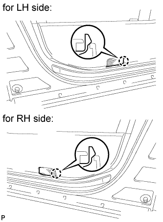
INSTALL LOWER DOOR FRAME GARNISH
-
Engage the 3 clips to install the lower door frame garnish.
-
-
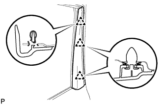
INSTALL FRONT DOOR LOWER FRAME BRACKET GARNISH
-
Engage the guide and 2 clips to install the front door lower frame bracket garnish.
-
-
CONNECT CABLE TO NEGATIVE BATTERY TERMINAL
Note
When disconnecting the cable, some systems need to be initialized after the cable is reconnected Click here.