CAN COMMUNICATION SYSTEM Open in One Side of CAN Branch Line
DESCRIPTION
If some ECUs and sensors are not displayed on the "Communication Bus Check" screen of the intelligent tester and some ECUs and sensors repeatedly appear and disappear on the screen when the CAN main bus wires are normal (there is no open, short, short to +B or short to GND in the main bus wires), there may be an open circuit in either of the CAN branch wires.
Tech Tips
If some ECUs and sensors repeatedly appear and disappear on the "Communication Bus Check" screen, communication between the normal ECUs and sensors and intelligent tester may be affected by the incomplete signals that are output from the ECU that has an open circuit in either of its CAN branch wires. In this case, the CAN branch wires for the ECUs and sensors that repeatedly appear and disappear from the screen are normal and the ECU that is not displayed on the screen may be the main cause of the problem (this ECU may have an open circuit in either of its CAN branch wires).
| Symptom | Trouble Area |
|---|---|
| 2 or more ECUs and/or sensors repeatedly appear and disappear on the "Communication Bus Check" screen of the intelligent tester. | One side of a pair of CAN branch wires is open for the affected system
|
Tech Tips
*1: w/ Navigation system
WIRING DIAGRAM
Refer to Check CAN Bus Lines for Short Circuit (for RHD Click here for LHD Click here.
INSPECTION PROCEDURE
Note
-
Turn the engine switch off before measuring the resistance of the CAN main wires and the CAN branch wires.
-
After the engine switch is turned off, check that the key reminder warning system and light reminder warning system are not in operation.
-
Before measuring the resistance, leave the vehicle as is for at least 1 minute and do not operate the engine switch, any other switches or doors. If any doors need to be opened in order to check the connectors, open the doors and leave them open.
Tech Tips
-
Operating the engine switch, any other switches or a door triggers related ECU and sensor communication on the CAN. This communication will cause the resistance value to change.
-
Even after DTCs are cleared, if a DTC is stored again after driving the vehicle for a while, the malfunction may be occurring due to vibration of the vehicle. In such a case, wiggling the ECUs or wire harness while performing the inspection below will help determine the cause of the malfunction.
PROCEDURE
-
CHECK FOR OPEN IN ONE SIDE OF CAN NO. 1 BUS BRANCH WIRE
-
Confirm the systems (ECUs and sensors), which use CAN communication, equipped on the vehicle Click here.
-
Using the intelligent tester, select and perform "Communication Bus Check" Click here.
-
Observe the screen for approximately 1 minute to check the ECUs and sensors that are not displayed on the screen and also those that repeatedly appear and disappear on the screen.
-
Disconnect the branch wire connectors, which are connected to the ECUs or sensors that never appear on the screen, from the CAN junction connector.
-
for RHD:
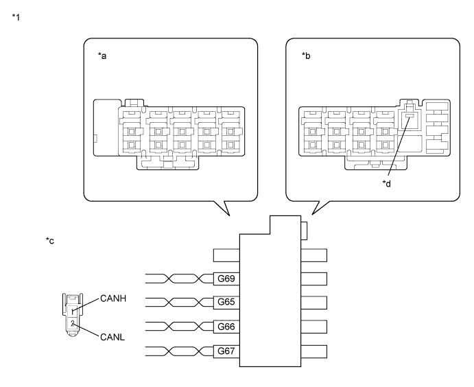
Text in Illustration *1 CAN No. 1 Junction Connector RH - - *a Junction Connector B Side *b Junction Connector A Side *c Front view of wire harness connector
(to CAN No. 1 Junction Connector RH)
*d Earth Terminal 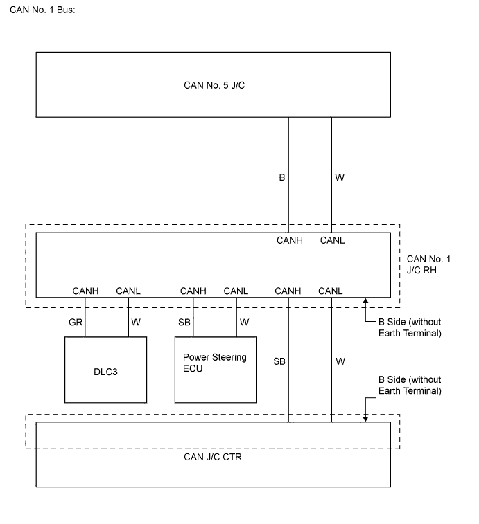
for CAN Junction Connector B Side Terminal No. (Symbol) Wiring Color Connected to G65-1 (CANH) SB Power steering ECU G65-2 (CANL) W G66-1 (CANH) GR DLC3 G66-2 (CANL) W G67-1 (CANH) SB CAN junction connector CTR G67-2 (CANL) W G69-1 (CANH) B CAN No. 5 junction connector G69-2 (CANL) W 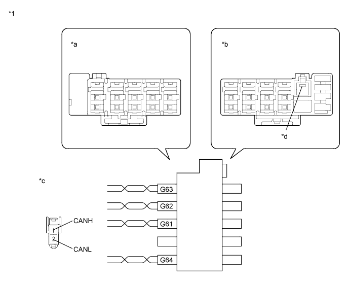
Text in Illustration *1 CAN Junction Connector CTR - - *a Junction Connector B Side *b Junction Connector A Side *c Front view of wire harness connector
(to CAN Junction Connector CTR)
*d Earth Terminal 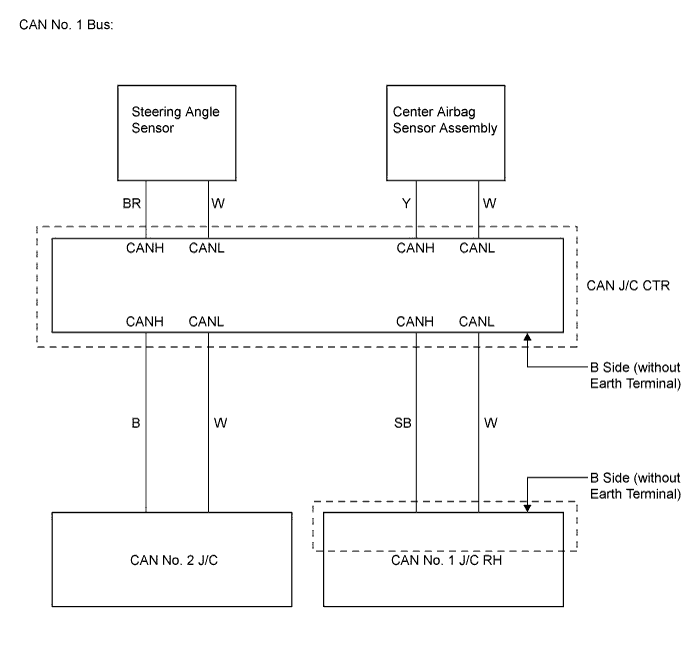
for CAN Junction Connector B Side Terminal No. (Symbol) Wiring Color Connected to G61-1 (CANH) B CAN No. 2 junction connector G61-2 (CANL) W G62-1 (CANH) SB CAN No. 1 junction connector RH G62-2 (CANL) W G63-1 (CANH) Y Center airbag sensor assembly G63-2 (CANL) W G64-1 (CANH) BR Steering angle sensor G64-2 (CANL) W 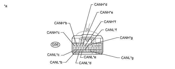
Terminal No. (Symbol) Wiring Color Connected to G56-1 (CANH) B ECM G56-12 (CANL) W G56-2 (CANH) B Brake actuator (Skid control ECU) G56-13 (CANL) W G56-3 (CANH) G Main body ECU G56-14 (CANL) W G56-4 (CANH) V Air conditioning amplifier G56-15 (CANL) W G56-5 (CANH) B CAN junction connector CTR G56-16 (CANL) W G56-7 (CANH) GR AFS ECU*1 G56-18 (CANL) W Tech Tips
*1: w/ AFS
Text in Illustration *a Front view of wire harness connector
(to CAN No. 2 Junction Connector)
*b to Skid Control ECU *c to ECM *d to Main Body ECU *e to A/C Amplifier *f to CAN J/C CTR *g to AFS ECU - - 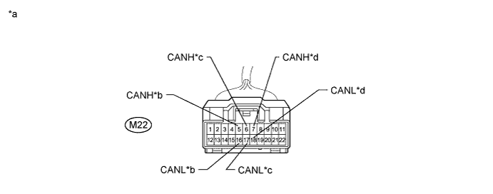
Terminal No. (Symbol) Wiring Color Connected to M22-6 (CANH) B CAN No. 1 junction connector RH M22-17 (CANL) W M22-5 (CANH) B Yaw rate and acceleration sensor M22-16 (CANL) W M22-7 (CANH) B Combination meter M22-18 (CANL) W Text in Illustration *a Front view of wire harness connector
(to CAN No. 5 Junction Connector)
*b to Yaw Rate and Acceleration Sensor *c to CAN No. 1 J/C RH *d to Combination Meter Tech Tips
-
Connecting locations of the connectors shown in the above tables are those of a vehicle whose connector locations have never been changed.
-
If the connector locations differ from those shown in the above tables, identify each connector according to the color of the bus wires.
-
-
for LHD:

Text in Illustration *1 CAN No. 1 Junction Connector RH - - *a Junction Connector B Side *b Junction Connector A Side *c Front view of wire harness connector
(to CAN No. 1 Junction Connector RH)
*d Earth Terminal 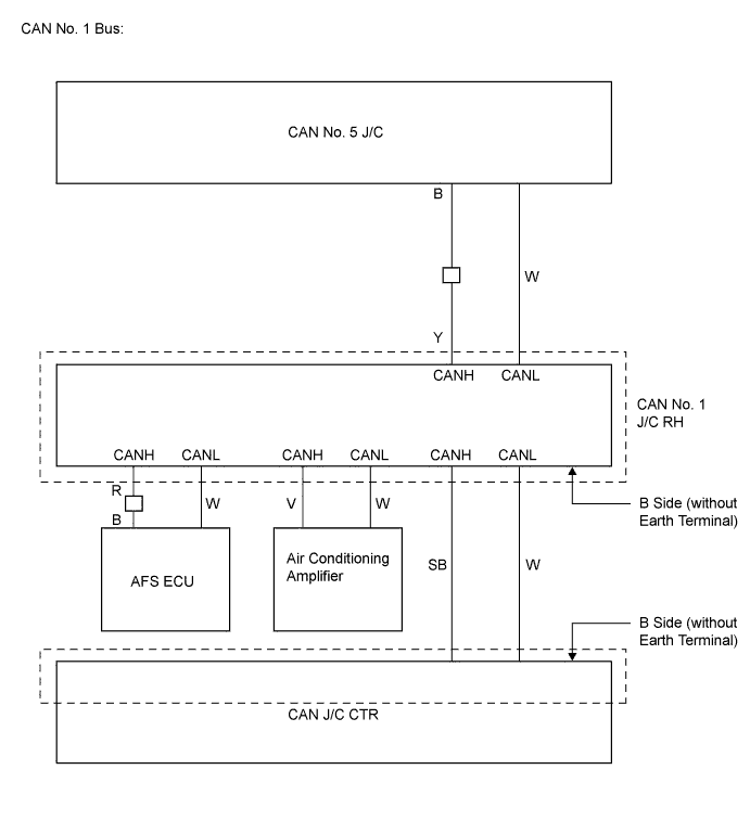
for CAN Junction Connector B Side Terminal No. (Symbol) Wiring Color Connected to G67-1 (CANH) SB CAN junction connector CTR G67-2 (CANL) W G87-1 (CANH) R AFS ECU G87-2 (CANL) W G88-1 (CANH) Y CAN No. 5 junction connector G88-2 (CANL) W G89-1 (CANH) V Air conditioning amplifier G89-2 (CANL) W 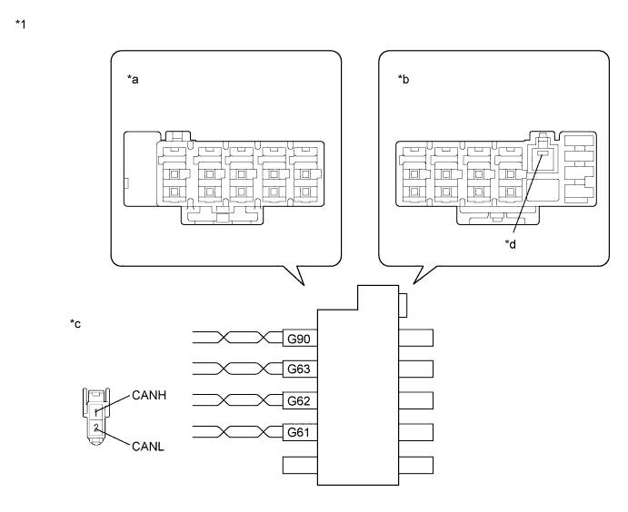
Text in Illustration *1 CAN Junction Connector CTR - - *a Junction Connector B Side *b Junction Connector A Side *c Front view of wire harness connector
(to CAN Junction Connector CTR)
*d Earth Terminal 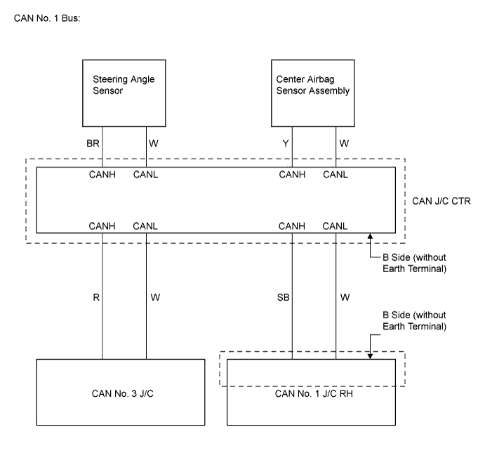
for CAN Junction Connector B Side Terminal No. (Symbol) Wiring Color Connected to G61-1 (CANH) R CAN No. 3 junction connector G61-2 (CANL) W G62-1 (CANH) SB CAN No. 1 junction connector RH G62-2 (CANL) W G63-1 (CANH) Y Center airbag sensor assembly G63-2 (CANL) W G90-1 (CANH) BR Steering angle sensor G90-2 (CANL) W 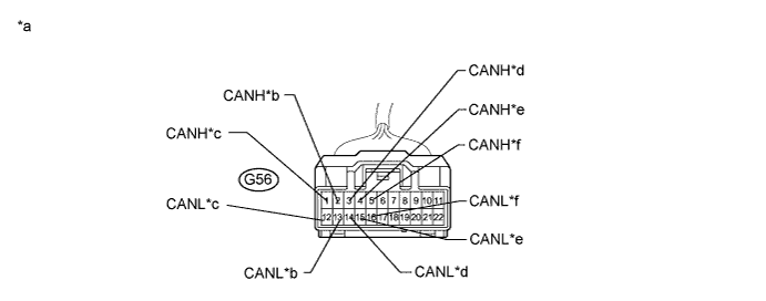
Terminal No. (Symbol) Wiring Color Connected to G56-1 (CANH) B CAN No. 6 junction connector G56-12 (CANL) W G56-2 (CANH) GR DLC3 G56-13 (CANL) W G56-3 (CANH) G Main body ECU G56-14 (CANL) W G56-4 (CANH) B Power steering ECU G56-15 (CANL) W G56-5 (CANH) B CAN No. 3 junction connector G56-16 (CANL) W Text in Illustration *a Front view of wire harness connector
(to CAN No. 2 Junction Connector)
*b DLC3 *c to CAN No. 6 Junction Connector *d to Main Body ECU *e to Power Steering ECU *f to CAN No. 3 Junction Connector 
Terminal No. (Symbol) Wiring Color Connected to F10-8 (CANH) R CAN junction connector CTR F10-19 (CANL) W F10-9 (CANH) R CAN No. 2 junction connector F10-20 (CANL) W F10-11 (CANH) B Navigation ECU*1 F10-22 (CANL) W Tech Tips
*1: w/ Navigation system
Text in Illustration *a Front view of wire harness connector
(to CAN No. 3 Junction Connector)
*b to CAN J/C CTR *c to CAN No. 2 J/C *d to Navigation ECU 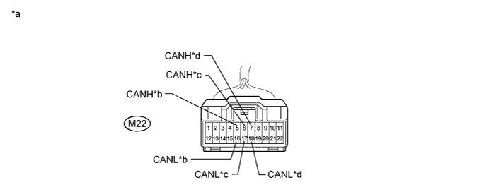
Terminal No. (Symbol) Wiring Color Connected to M22-6 (CANH) B CAN No. 1 junction connector RH M22-17 (CANL) W M22-5 (CANH) B Yaw rate and acceleration sensor M22-16 (CANL) W M22-7 (CANH) B Combination meter M22-18 (CANL) W Text in Illustration *a Front view of wire harness connector
(to CAN No. 5 Junction Connector)
*b to Yaw Rate and Acceleration Sensor *c to CAN No. 1 J/C RH *d to Combination Meter 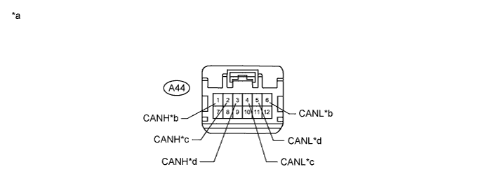
Terminal No. (Symbol) Wiring Color Connected to A44-1 (CANH) L ECM A44-6 (CANL) Y A44-2 (CANH) V Brake actuator (Skid control ECU) A44-4 (CANL) P A44-3 (CANH) B CAN No. 2 junction connector A44-5 (CANL) W Text in Illustration *a Front view of wire harness connector
(to CAN No. 6 Junction Connector)
*b to ECM *c to Skid Control ECU *d to CAN No. 2 J/C Tech Tips
-
Connecting locations of the connectors shown in the above tables are those of a vehicle whose connector locations have never been changed.
-
If the connector locations differ from those shown in the above tables, identify each connector according to the color of the bus wires.
-
-
-
Check that the ECUs and sensors, which repeatedly appeared and disappeared on the "Communication Bus Check" screen, are constantly displayed.
-
Perform the communication stop mode check for the ECUs and sensors which correspond to the disconnected branch wire connectors Click here.
Tech Tips
If any of the following conditions are met, an open in the CAN bus main wire is suspected. Refer to Open in CAN Main Bus Line (for RHD Click here for LHD Click here.
-
Only ECM is not displayed for 1 minute.
-
Only combination meter is not displayed for 1 minute.
-
All ECUs and sensors connected to the CAN No.2 and CAN No. 5 junction connector are not displayed for 1 minute.
-
NEXT 
INSPECT CORRESPONDING COMMUNICATION STOP MODE Click here
-