STEERING COLUMN ASSEMBLY INSTALLATION

-
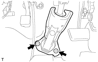
INSTALL STEERING COLUMN ASSEMBLY
-
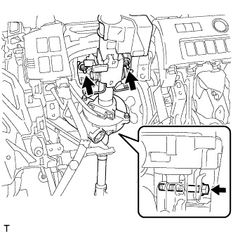
Install the steering column assembly with the bolt and 2 nuts.
- Torque:
- Bolt
- 36 N*m { 367 kgf*cm, 26 ft.*lbf }
- Nut
- 25 N*m { 255 kgf*cm, 18 ft.*lbf }
-
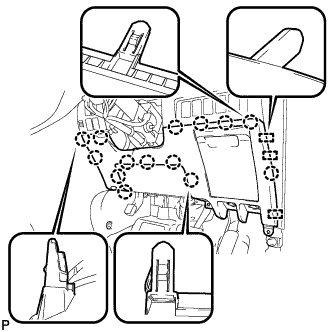
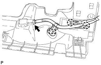
Connect the connectors and wire harness clamps to the steering column assembly.
-
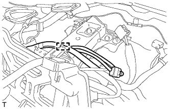
Engage the wire harness clamp.
-
-
CONNECT BRAKE MASTER CYLINDER PUSH ROD CLEVIS
-
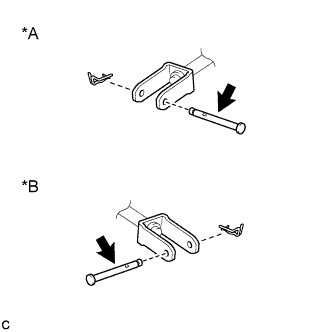
Text in Illustration *A for LHD *B for RHD 
Lithium Soap Base Glycol Grease Apply lithium soap base glycol grease to the contact surface of the brake master cylinder push rod clevis pin.
-
Connect the brake master cylinder push rod clevis to the brake pedal support assembly with the brake master cylinder push rod clevis pin and a new clip.
-
-
CONNECT NO. 2 STEERING INTERMEDIATE SHAFT ASSEMBLY
-
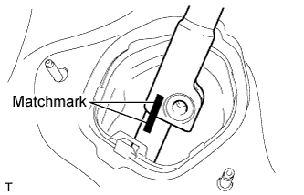
Align the matchmarks on the No. 2 steering intermediate shaft assembly and the steering intermediate shaft assembly.
-
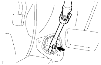
Connect the No. 2 steering intermediate shaft assembly to the steering intermediate shaft assembly, and install the bolt.
- Torque:
- 35 N*m { 360 kgf*cm, 26 ft.*lbf }
-
-
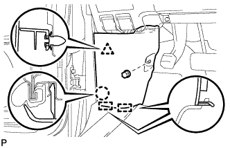
INSTALL COLUMN HOLE COVER SILENCER SHEET
-
Install the column hole cover silencer sheet with the 2 clips.
-
-
INSTALL POWER STEERING ECU ASSEMBLY
-
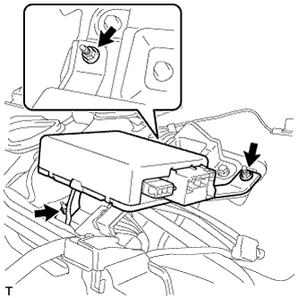
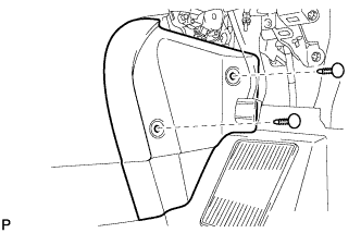
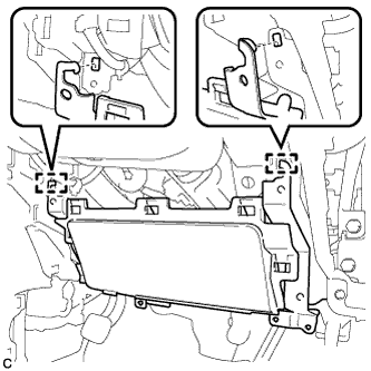
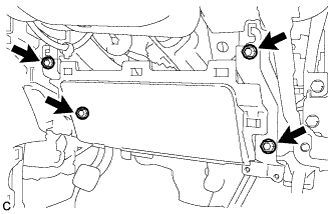
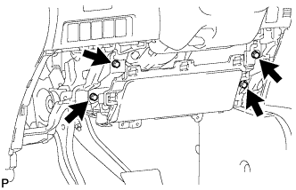
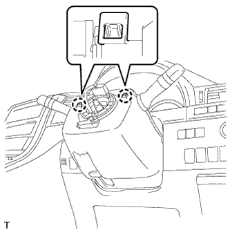
Install the power steering ECU assembly with the 3 nuts.
- Torque:
- 8.0 N*m { 82 kgf*cm, 71 in.*lbf }
-
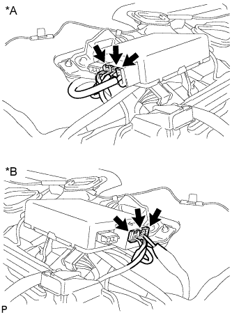
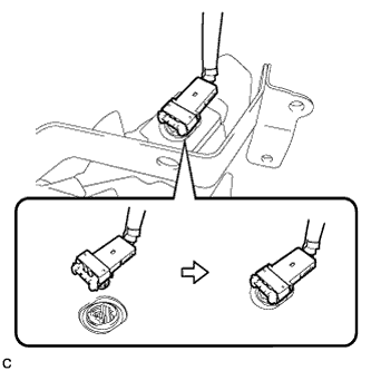
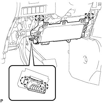
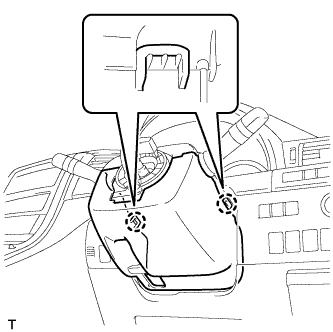
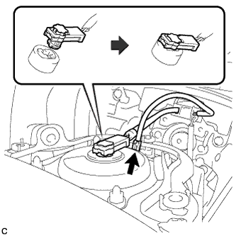
Text in Illustration *A for LHD *B for RHD Connect the 3 connectors to the power steering ECU assembly.
-
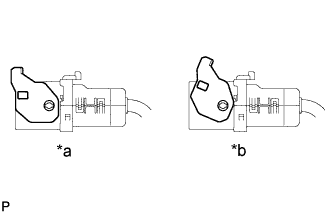
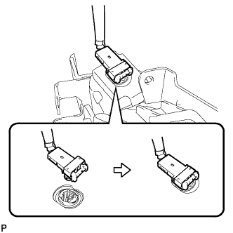
Text in Illustration *a OK *b NG Inspect that the lock lever of the connector is released completely.
Note
If the lock lever is not released completely, the connector may not be connected securely to the power steering ECU assembly.
-
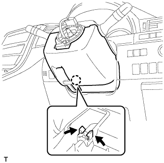
Securely connect the connector to the power steering ECU assembly.
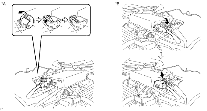
Text in Illustration *A for LHD *B for RHD Tech Tips
Return the lock lever to its original position to connect the connector, and then securely push in the lock of the lock lever as shown in the illustration.
-
-
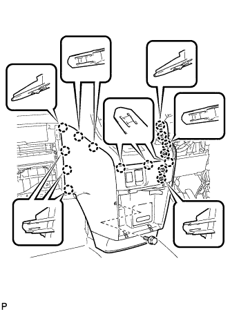
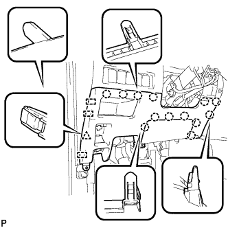
INSTALL UPPER INSTRUMENT PANEL SUB-ASSEMBLY
Tech Tips
It is possible to install the instrument panel register assembly with the upper instrument panel sub-assembly still installed to the vehicle body. Refer to the reassembly procedure for the upper instrument panel sub-assembly.
-
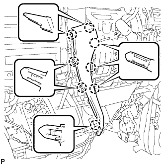
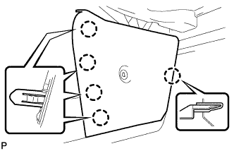
Engage the 5 claws.
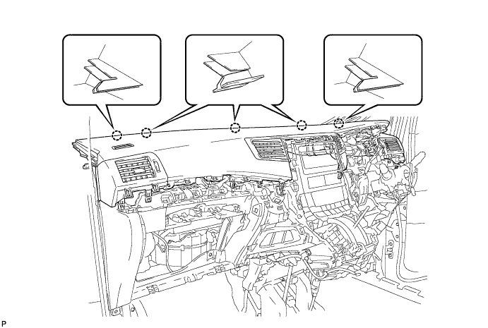
Note
-
Do not allow the wire harness to get caught in the claws.
-
Make sure that the claws are fully engaged.
-
-
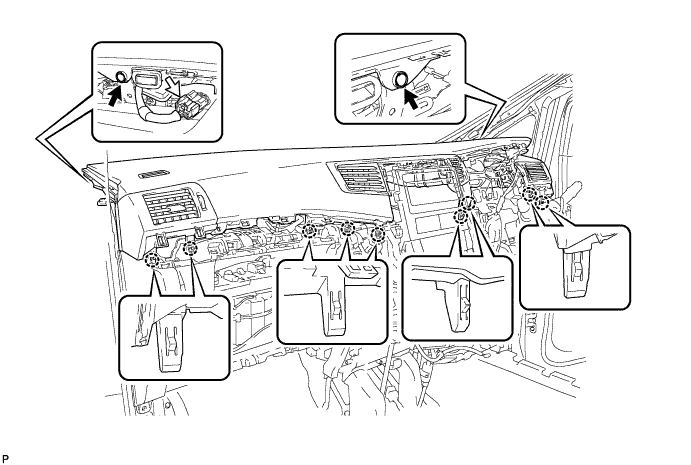
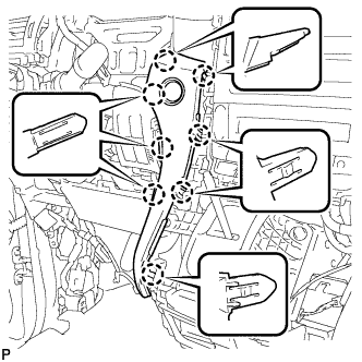
Engage the 9 claws.
-
Install the 2 clips.
-
Connect the connector.
-
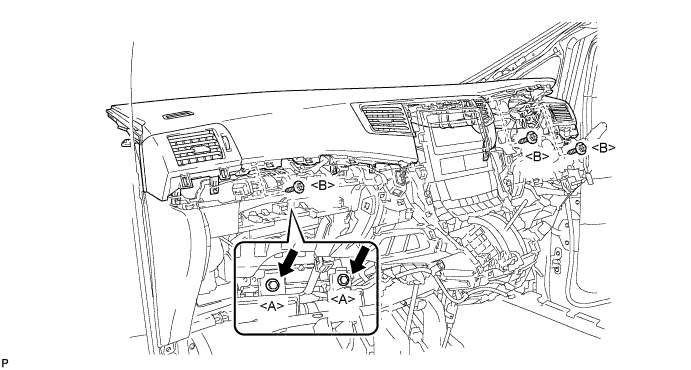
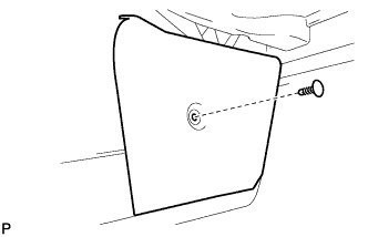
Install the 2 passenger airbag bolts <A>.
- Torque:
- 20 N*m { 204 kgf*cm, 15 ft.*lbf }
-
Install the upper instrument panel sub-assembly with the 3 screws <B>.
-
-
CONNECT INSTRUMENT PANEL WIRE ASSEMBLY
-
Check that the engine switch is off.
-
Check that the cable is disconnected from the negative (-) battery terminal.
CAUTION:
Wait at least 90 seconds after disconnecting the cable from the negative (-) battery terminal to disable the SRS system.
-
Connect the connector.
Note
When connecting the airbag connector, take care not to damage the airbag wire harness.
-
Engage the wire harness clamp.
-
-
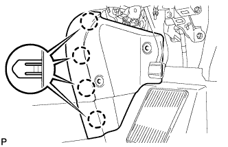
INSTALL NO. 1 INSTRUMENT PANEL BOX DOOR SUB-ASSEMBLY
-
Engage the 6 claws to install the No. 1 instrument panel box door sub-assembly.
-
Connect the connector.
-
-
INSTALL NO. 3 INSTRUMENT CLUSTER FINISH PANEL GARNISH
-
Engage the 16 claws to install the No. 3 instrument cluster finish panel garnish.
Note
Make sure that the claws are fully engaged.
-
-
INSTALL NO. 2 INSTRUMENT CLUSTER FINISH PANEL GARNISH (for RHD)
-
Engage the 8 claws to install the No. 2 instrument cluster finish panel garnish.
Note
Make sure that the claws are fully engaged.
-
-
INSTALL NO. 2 INSTRUMENT CLUSTER FINISH PANEL GARNISH (for LHD)
-
Engage the 8 claws to install the No. 2 instrument cluster finish panel garnish.
Note
Make sure that the claws are fully engaged.
-
-
INSTALL CENTER INSTRUMENT CLUSTER FINISH PANEL SUB-ASSEMBLY
-
Connect the connector.
-
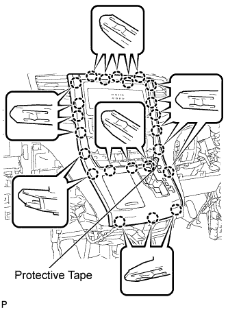
Engage the 23 claws to install the center instrument cluster finish panel sub-assembly.
Note
-
When installing the center instrument cluster finish panel sub-assembly, make sure to press the upper middle part firmly.
-
Make sure that the claws are fully engaged.
-
-
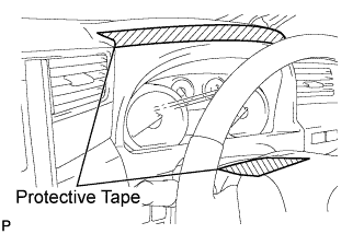
Remove the applied protective tape.
-
Move the shift lever to P.
-
-
INSTALL SHIFT LEVER KNOB SUB-ASSEMBLY
-
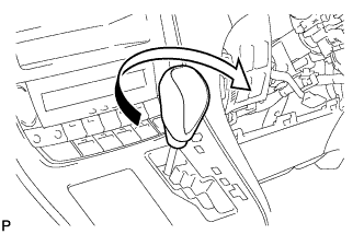
Turn the shift lever knob clockwise to install the shift lever knob sub-assembly.
-
-
INSTALL INSTRUMENT CLUSTER FINISH PANEL ASSEMBLY
-
Engage the 15 claws.
Tech Tips
Before engaging the 15 claws, make sure that the claws are positioned correctly.
Note
Make sure that the claws are fully engaged.
-
Install the instrument cluster finish panel assembly with the bolt <C>.
-
-
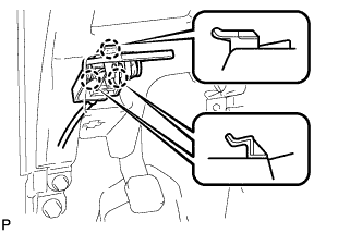
INSTALL INSTRUMENT PANEL BOX ASSEMBLY
-
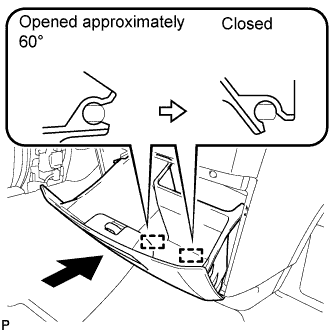
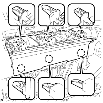
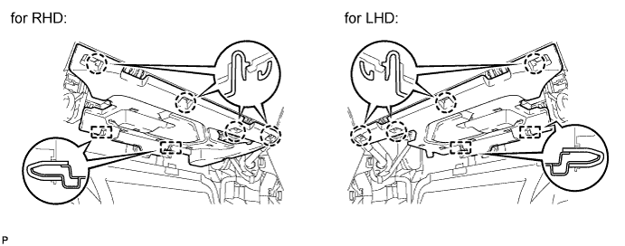
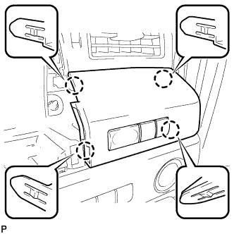
With the instrument panel box assembly opened approximately 60° from its closed position, engage the 2 hinges horizontally.
Note
Engaging the hinges from the top will deform the hinges. Be sure to install the instrument panel box assembly horizontally.
-
Install the damper clip.
-
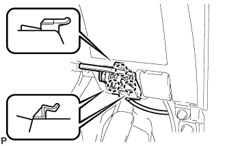
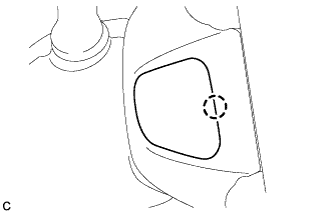
Slightly bend stoppers (A) and (B) in the directions indicated by the arrows in the illustration and engage the stoppers to install the instrument panel box assembly.
-
-
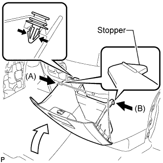
INSTALL GLOVE COMPARTMENT DOOR ASSEMBLY
-
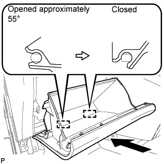
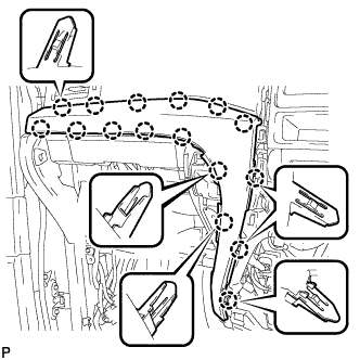
With the glove compartment door assembly opened approximately 55° from its closed position, engage the 2 hinges horizontally.
Note
Engaging the hinges from the top will deform the hinges. Be sure to install the glove compartment door assembly horizontally.
-
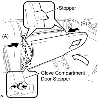
Slightly bend stoppers (A) and (B) in the directions indicated by the arrows in the illustration and engage the stoppers to install the glove compartment door assembly.
-
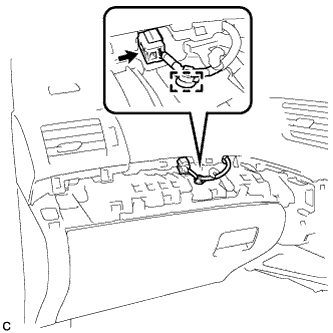
Engage the claw and connect the glove compartment door stopper.
-
-
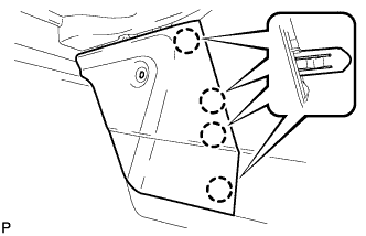
INSTALL NO. 2 INSTRUMENT PANEL UNDER COVER SUB-ASSEMBLY
-
Connect the connector.
-
Engage the 2 guides.
-
Engage the 4 claws to install the No. 2 instrument panel under cover sub-assembly.
Note
Make sure that the claws are fully engaged.
-
-
INSTALL CENTER FLOOR CARPET COVER LH
-
Engage the 4 claws.
-

Install the center floor carpet cover LH with the clip.
-
-
INSTALL CENTER FLOOR CARPET COVER RH (for RHD)
-
Engage the 4 claws.
-
Install the center floor carpet cover RH with the 2 clips.
-
-
INSTALL CENTER FLOOR CARPET COVER RH (for LHD)
-
Engage the 5 claws.
-
Install the center floor carpet cover RH with the clip.
-
-
INSTALL DRIVER SIDE KNEE AIRBAG ASSEMBLY (for RHD)
-
Check that the engine switch is off.
-
Check that the cable is disconnected from the negative (-) battery terminal.
CAUTION:
Wait at least 90 seconds after disconnecting the cable from the negative (-) battery terminal to disable the SRS system.
-
Connect the connector to the driver side knee airbag assembly.
Note
When connecting the airbag connector, take care not to damage the airbag wire harness.
-
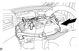
Engage the 2 hooks and temporarily install the driver side knee airbag assembly.
-
Install the driver side knee airbag assembly with the 4 bolts firmly.
- Torque:
- 10 N*m { 102 kgf*cm, 7 ft.*lbf }
-
-
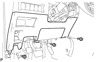
INSTALL DRIVER SIDE KNEE AIRBAG ASSEMBLY (for LHD)
-
Check that the engine switch is off.
-
Check that the cable is disconnected from the negative (-) battery terminal.
CAUTION:
Wait at least 90 seconds after disconnecting the cable from the negative (-) battery terminal to disable the SRS system.
-
Connect the connector to the driver side knee airbag assembly.
Note
When connecting the airbag connector, take care not to damage the airbag wire harness.
-
Engage the 2 hooks and temporarily install the driver side knee airbag assembly.
-
Engage the 2 claws to install the DLC3.
-
Install the driver side knee airbag assembly with the 4 bolts firmly.
- Torque:
- 10 N*m { 102 kgf*cm, 7 ft.*lbf }
-
-
INSTALL LOWER INSTRUMENT PANEL FINISH PANEL (for RHD)
-
Engage the 3 guides and 14 claws.
Tech Tips
Make sure that all claws around the entire circumference of the driver side knee airbag assembly are fully engaged.
Note
Make sure that the claws are fully engaged.
-
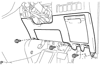
Install the lower instrument panel finish panel with the 3 screws <B>.
-

Engage the 3 claws and the fuel lid lock control cable assembly.
-
Engage the 3 claws and the hood lock control cable assembly.
-
-
INSTALL LOWER INSTRUMENT PANEL FINISH PANEL (for LHD)
-
Engage the 3 guides, 13 claws and clip.
Tech Tips
Make sure that all claws around the entire circumference of the driver side knee airbag assembly are fully engaged.
Note
Make sure that the claws are fully engaged.
-
Install the lower instrument panel finish panel with the 3 screws <B>.
-

Connect the fuel filler opening lid lock sub-assembly to the fuel lid lock open lever sub-assembly.
-
Engage the 3 claws and the fuel lid lock control cable assembly.
-

Engage the 3 claws and the hood lock control cable assembly.
-
-
INSTALL NO. 1 INSTRUMENT PANEL UNDER COVER SUB-ASSEMBLY (for RHD)
-
Engage the 2 claws and DLC3.
-
Engage the clamp.
-
Connect the connector.
-

Engage the 2 claws and 2 guides.
Note
Make sure that the claws are fully engaged.
-
Install the No. 1 instrument panel under cover sub-assembly with the 2 screws <B>.
-
-
INSTALL NO. 1 INSTRUMENT PANEL UNDER COVER SUB-ASSEMBLY (for LHD)
-
Engage the clamp.
-
Connect each connector.
-

Engage the 2 claws and guide.
Note
Make sure that the claws are fully engaged.
-
Install the No. 1 instrument panel under cover sub-assembly with the 2 screws <B>.
-
-
INSTALL NO. 1 INSTRUMENT CLUSTER FINISH PANEL GARNISH
-
Connect the connector.
-
Engage the 4 claws to install the No. 1 instrument cluster finish panel garnish.
-
-
INSTALL COMBINATION METER ASSEMBLY
-
Connect the connector and temporarily install the combination meter assembly.
Note
When installing the combination meter assembly, do not damage the upper instrument panel sub-assembly and combination meter assembly.
-
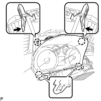
Engage the 4 claws to install the combination meter assembly.
-
-
INSTALL NO. 1 INSTRUMENT CLUSTER FINISH PANEL
-
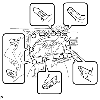
Engage the 11 claws and 2 guides to install the No. 1 instrument cluster finish panel.
-
Remove the protective tape from the steering column cover.
-
-
INSTALL FRONT LOWER PILLAR GARNISH RH
-
Engage the 4 claws to install the front lower pillar garnish RH.
-
-
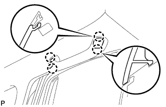
INSTALL FRONT PILLAR GARNISH RH
-
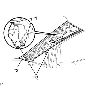
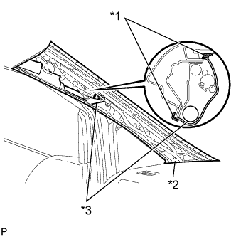
Text in Illustration *1 Protective Tape *2 Protective Cover *3 Curtain Shield Airbag Assembly Remove the protective cover.
-
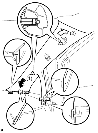
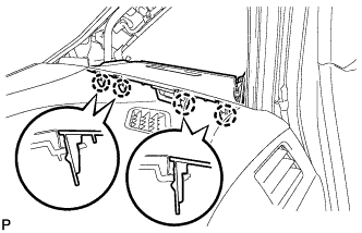
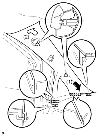
Engage the 6 guides and 2 clips to install the front pillar garnish RH.
-
-
INSTALL NO. 1 ASSIST GRIP (for RH Side)
-
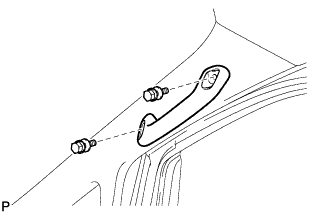
Install the No. 1 assist grip with the 2 bolts.
-
-
INSTALL ASSIST GRIP PLUG (for Front RH)
-
Engage the 4 claws to install the 2 assist grip plugs.
-
-
INSTALL FRONT DOOR OPENING TRIM WEATHERSTRIP RH
-
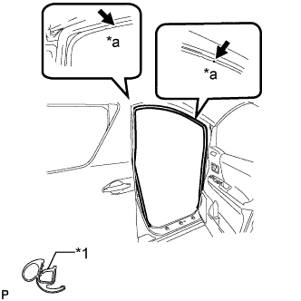
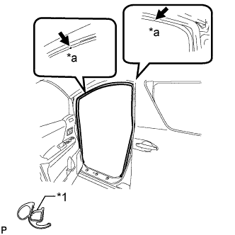
Text in Illustration *1 Alignment Mark *a White Align the alignment marks on the weatherstrip with the protruding portions on the body indicated by the arrows in the illustration, and install the front door opening trim weatherstrip RH.
Note
After installation, check that the corners fit correctly.
-
-
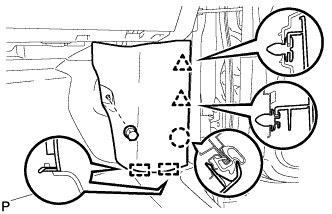
INSTALL COWL SIDE TRIM BOARD RH (for RHD)
-

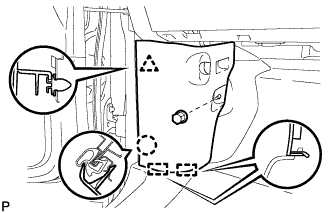
Engage the 2 guides, claw and clip to install the cowl side trim board RH.
-
Install the clip(A).
-
-
INSTALL COWL SIDE TRIM BOARD RH (for LHD)
-
Engage the 2 guides, claw and the 2 clips to install the cowl side trim board RH.
-
Install the clip(A).
-
-
INSTALL FRONT LOWER PILLAR GARNISH LH
Tech Tips
Use the same procedure for the LH side and RH side.
-
INSTALL FRONT PILLAR GARNISH LH
-
Text in Illustration *1 Protective Tape *2 Protective Cover *3 Curtain Shield Airbag Assembly Remove the protective cover.
-
Engage the 6 guides and 2 clips, then install the front pillar garnish LH.
-
-
INSTALL NO. 1 ASSIST GRIP (for LH Side)
Tech Tips
Use the same procedure for the LH side and RH side.
-
INSTALL ASSIST GRIP PLUG (for Front LH)
Tech Tips
Use the same procedure for the LH side and RH side.
-
INSTALL FRONT DOOR OPENING TRIM WEATHERSTRIP LH
-
Text in Illustration *1 Alignment Mark *a Yellow Green Align the alignment marks on the weatherstrip with the protruding portions on the body indicated by the arrows in the illustration, and install the front door opening trim weatherstrip LH.
Note
After installation, check that the corners fit correctly.
-
-
INSTALL COWL SIDE TRIM BOARD LH (for RHD)
-
Engage the 2 guides, claw and clip to install the cowl side trim board LH.
-
Install the clip(A).
-
-
INSTALL COWL SIDE TRIM BOARD LH (for LHD)
-
Engage the 2 guides, claw and clip to install the cowl side trim board LH.
-
Install the clip(A).
-
-
ALIGN FRONT WHEELS FACING STRAIGHT AHEAD
-
INSTALL TURN SIGNAL SWITCH ASSEMBLY WITH SPIRAL CABLE SUB-ASSEMBLY
-
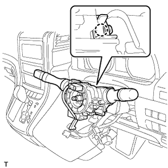
Using pliers, release the clamp, and then engage the claw to install the turn signal switch assembly with spiral cable sub-assembly to the steering column assembly.
-
Connect the connectors to the turn signal switch assembly with spiral cable sub-assembly.
-
-
INSTALL UPPER STEERING COLUMN COVER
Note
Installing the upper steering column cover in the incorrect order may break the claw and cause clearance between the upper steering column cover and lower steering column cover.
-
Engage the 4 clips and the 2 claws to install the upper steering column cover to the lower instrument cover.
-
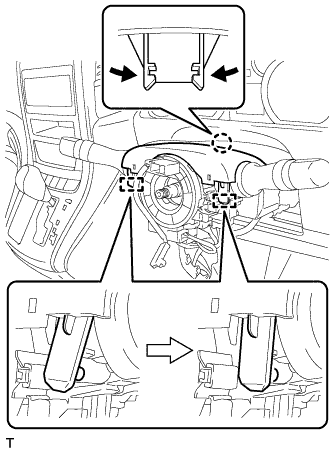
Engage the claw and 2 pins to install the upper steering column cover to the steering column assembly.
-
-
INSTALL LOWER STEERING COLUMN COVER
Note
Installing the lower steering column cover in the incorrect order may break the claw and cause clearance between the upper steering column cover and lower steering column cover.
-
Engage the 2 claws to install the lower steering column cover to the upper steering column cover.
-
Engage the 2 claws.
-
Engage the claw.
Note
Press the area around the claw to engage it.
-
-
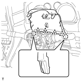
ADJUST SPIRAL CABLE
-
Check that the engine switch is off.
-
Check that the cable is disconnected from the negative (-) battery terminal.
CAUTION:
Wait at least 90 seconds after disconnecting the cable from the negative (-) battery terminal to disable the SRS system.
-
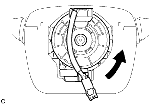
Rotate the spiral cable counterclockwise slowly by hand until it stops.
Note
Do not turn the spiral cable using the airbag wire harness.
-
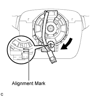
Rotate the spiral cable clockwise approximately 2.5 turns to align the marks.
Note
Do not turn the spiral cable using the airbag wire harness.
Tech Tips
The spiral cable will rotate approximately 2.5 turns to both the left and right from the center.
-
-
INSTALL STEERING WHEEL ASSEMBLY
-
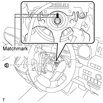
Align the matchmarks on the steering wheel assembly and steering main shaft.
-
Install the steering wheel assembly set nut.
- Torque:
- 50 N*m { 510 kgf*cm, 37 ft.*lbf }
-
Connect the connectors to the spiral cable sub-assembly.
-
-
INSPECT STEERING WHEEL CENTER POINT
-
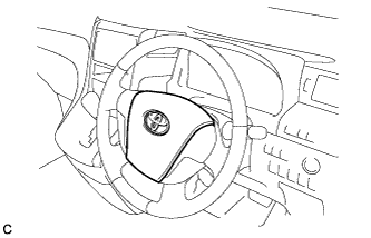
INSTALL STEERING PAD
-
Check that the engine switch is off.
-
Check that the cable is disconnected from the negative (-) battery terminal.
CAUTION:
Wait at least 90 seconds after disconnecting the cable from the negative (-) battery terminal to disable the SRS system.
-
Connect the airbag connector to the steering pad.
Note
When connecting the airbag connector, take care not to damage the airbag wire harness.
-
Connect the horn connector to the steering pad.
-

Confirm that the circumference groove of each "TORX" screw fits in the screw case, and place the steering pad onto the steering wheel assembly.
-
Using a "TORX" socket wrench (T30), tighten the 2 "TORX" screws.
- Torque:
- 8.8 N*m { 90 kgf*cm, 78 in.*lbf }
-
-
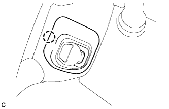
INSTALL LOWER NO. 3 STEERING WHEEL COVER
-
Engage the claw to install the lower No. 3 steering wheel cover.
-
-
INSTALL LOWER NO. 2 STEERING WHEEL COVER
-
Engage the claw to install the lower No. 2 steering wheel cover.
-
-
CONNECT CABLE TO NEGATIVE BATTERY TERMINAL
Note
-
Make sure that the cable has been disconnected from the battery terminal for at least 2 seconds before reconnecting the cable.
-
Connect the cable to negative (-) battery terminal with the front wheels facing straight ahead.
-
When disconnecting the cable, some systems need to be initialized after the cable is reconnected Click here.
-
-
INSPECT STEERING PAD
-
Visually check for defects with the steering pad installed on the vehicle.
-
The defects are as follows:
-
Cuts on the surface and in the grooves of the steering pad
-
Small cracks on the surface and in the grooves of the steering pad
-
Significant discoloration on the surface and in the grooves of the steering pad
OK No defects are found. Tech Tips
If any of the defects is found, replace the steering pad with a new one.
-
-
-
Make sure that the horn sounds.
Tech Tips
If the horn does not sound, inspect the horn system Click here.
-
-
INITIALIZE ROTATION ANGLE SENSOR AND CALIBRATE TORQUE SENSOR ZERO POINT
-
REGISTER ECU CODE
Note
When replacing the steering lock actuator assembly, perform initialization.
-
INSPECT SRS WARNING LIGHT