STEERING COLUMN ASSEMBLY REMOVAL

CAUTION:
Some of these service operations may affect the SRS airbag system. Read the precautionary notices concerning the SRS airbag system before servicing Click here.
-
PRECAUTION
-
ALIGN FRONT WHEELS FACING STRAIGHT AHEAD
-
DISCONNECT CABLE FROM NEGATIVE BATTERY TERMINAL
CAUTION:
Wait at least 90 seconds after disconnecting the cable from the negative (-) battery terminal to disable the SRS system.
Note
When disconnecting the cable, some systems need to be initialized after the cable is reconnected Click here.
-
REMOVE LOWER NO. 3 STEERING WHEEL COVER
-
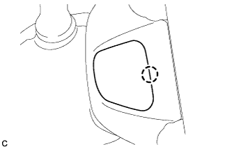
Disengage the claw to remove the lower No. 3 steering wheel cover.
-
-
REMOVE LOWER NO. 2 STEERING WHEEL COVER
-
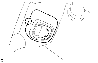
Disengage the claw to remove the lower No. 2 steering wheel cover.
-
-
REMOVE STEERING PAD
-
Check that the engine switch is off.
-
Check that the cable is disconnected from the negative (-) battery terminal.
CAUTION:
Wait at least 90 seconds after disconnecting the cable from the negative (-) battery terminal to disable the SRS system.
-
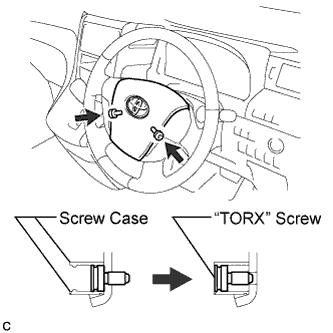
Using a "TORX" socket wrench (T30), loosen the 2 "TORX" screws until the circumference groove catches on the screw case.
-
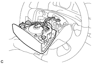
Pull out the steering pad from the steering wheel assembly.
Note
When removing the steering pad, do not pull the airbag wire harness.
-
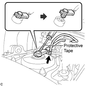
Using a screwdriver with the tip wrapped with protective tape, disconnect the airbag connector from the steering pad.
Note
When disconnecting the airbag connector, take care not to damage the airbag wire harness.
-
Disconnect the horn connector to remove the steering pad.
-
-
REMOVE STEERING WHEEL ASSEMBLY
-
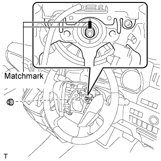
Remove the steering wheel assembly set nut.
-
Put matchmarks on the steering wheel assembly and the steering main shaft.
-
Disconnect the connectors from the spiral cable.
-
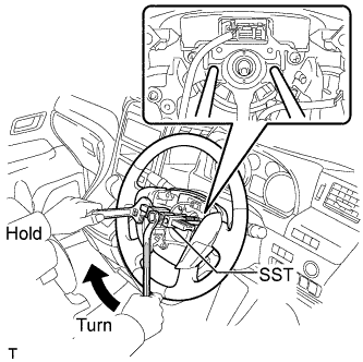
Install SST to the steering wheel assembly as shown in the illustration.
- SST
- 09950-50013 ( 09951-05010, 09952-05010, 09953-05020, 09954-05070 )
Note
Apply a small amount of grease to the threads and tip of SST (09953-05020) before use.
-
Using SST, remove the steering wheel assembly.
-
-
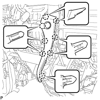
REMOVE LOWER STEERING COLUMN COVER
Note
Removing the lower steering column cover in the incorrect order will cause the lower steering column cover to break.
-
Release the tilt and telescopic lever, and fully extend and lower the steering column assembly.
-
Lock the tilt and telescopic lever.
-
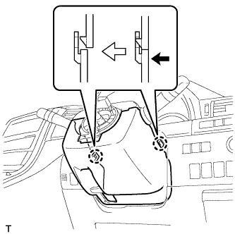
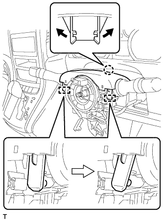
Push the right and left sides of the lower steering column cover, and disengage the 2 claws.
Note
Completely disengage the claws.
-
Use your fingers to disengage the claw through the tilt lever opening on the lower steering column cover.
Tech Tips
Spread the claw to disengage it.
-
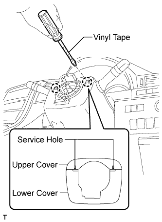
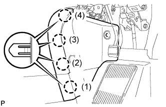
Using a screwdriver, insert the tip into each service hole to disengage the 2 claws, and remove the lower steering column cover as shown in the illustration.
Tech Tips
Tape the screwdriver tip before use.
-
-
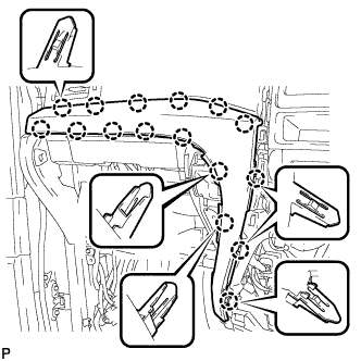
REMOVE UPPER STEERING COLUMN COVER
-
Disengage the claw and the 2 pins, and separate the upper steering column cover from the steering column assembly.
-
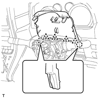
Disengage the 4 clips and 2 claws to remove the upper steering column cover from the lower instrument cover.
-
-
REMOVE TURN SIGNAL SWITCH ASSEMBLY WITH SPIRAL CABLE SUB-ASSEMBLY
-
Disconnect the connectors from the turn signal switch assembly with spiral cable sub-assembly.
-
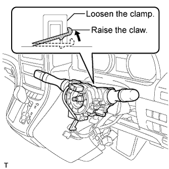
Using pliers, loosen the clamp and raise the claw. Remove the turn signal switch assembly with spiral cable sub-assembly from the steering column assembly.
-
-
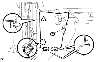
REMOVE COWL SIDE TRIM BOARD RH (for RHD)
-

Remove the clip.
-
Disengage the clip, claw and 2 guides, and remove the cowl side trim board RH.
-
-
REMOVE COWL SIDE TRIM BOARD RH (for LHD)
-
Remove the clip.
-
Disengage the 2 clips, claw and 2 guides, and remove the cowl side trim board RH.
-
-
REMOVE FRONT DOOR OPENING TRIM WEATHERSTRIP RH
-
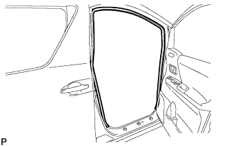
Remove the front door opening trim weatherstrip RH.
-
-
REMOVE ASSIST GRIP PLUG (for Front RH)
-
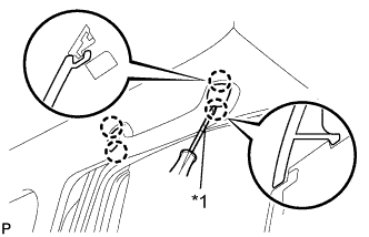
Text in Illustration *1 Protective Tape Using a screwdriver, disengage the 4 claws and remove the 2 assist grip plugs.
Tech Tips
Tape the screwdriver tip before use.
-
-
REMOVE NO. 1 ASSIST GRIP (for RH Side)
-
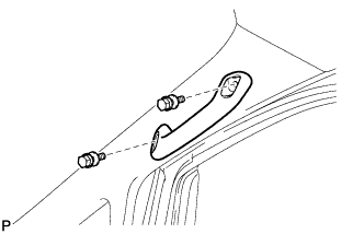
Remove the 2 bolts and the No. 1 assist grip.
-
-
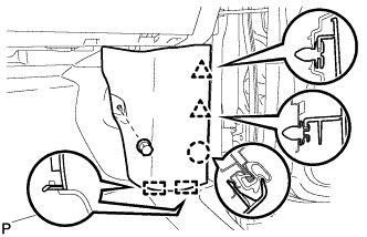
REMOVE FRONT PILLAR GARNISH RH
-
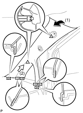
Pull the upper part of the garnish toward the inside of the cabin and disengage the 2 clips.
-
Disengage the 6 guides and remove the front pillar garnish RH.
-
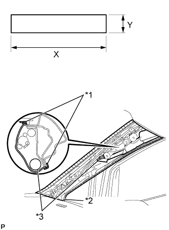
Text in Illustration *1 Adhesive Tape *2 Protective Cover *3 Curtain Shield Airbag Assembly Protect the curtain shield airbag assembly.
-
Cover the airbag with a cloth or piece of nylon and secure the ends of the cover with tape as shown in the illustration.
Protective Cover size X 700 mm (27.56 in.) Y 120 mm (4.72 in.) Note
Cover the curtain shield airbag assembly with a protective cover as soon as the front pillar garnish is removed.
-
-
-
REMOVE FRONT LOWER PILLAR GARNISH RH
-
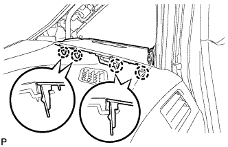
Disengage the 4 claws and remove the front lower pillar garnish RH .
-
-
REMOVE COWL SIDE TRIM BOARD LH (for RHD)
-
Remove the clip(A).
-
Disengage the clip, claw and 2 guides, and remove the cowl side trim board LH.
-
-
REMOVE COWL SIDE TRIM BOARD LH (for LHD)
-
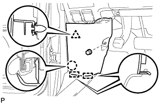
Remove the clip(A).
-
Disengage the clip, claw and 2 guides, and remove the cowl side trim board LH.
-
-
REMOVE FRONT DOOR OPENING TRIM WEATHERSTRIP LH
Tech Tips
Use the same procedure for the LH side and RH side.
-
REMOVE ASSIST GRIP PLUG (for Front LH)
Tech Tips
Use the same procedure for the LH side and RH side.
-
REMOVE NO. 1 ASSIST GRIP (for LH Side)
Tech Tips
Use the same procedure for the LH side and RH side.
-
REMOVE FRONT PILLAR GARNISH LH
-
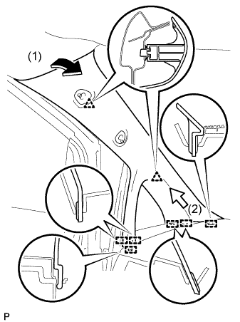
Pull the upper part of the garnish toward the inside of the cabin and disengage the 2 clips.
-
Disengage the 6 guides and remove the front pillar garnish LH.
-
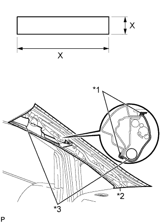
Text in Illustration *1 Adhesive Tape *2 Protective Cover *3 Curtain Shield Airbag Assembly Protect the curtain shield airbag assembly.
-
Cover the airbag with a cloth or piece of nylon and secure the ends of the cover with tape as shown in the illustration.
Protective Cover size X 700 mm (27.56 in.) Y 120 mm (4.72 in.) Note
Cover the curtain shield airbag assembly with a protective cover as soon as the front pillar garnish is removed.
-
-
-
REMOVE FRONT LOWER PILLAR GARNISH LH
Tech Tips
Use the same procedure for the LH side and RH side.
-
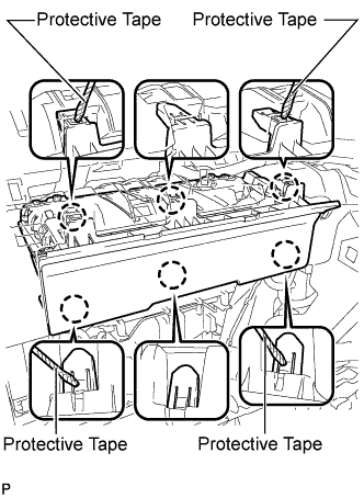
REMOVE NO. 1 INSTRUMENT CLUSTER FINISH PANEL
-
Operate the tilt lever to lower the steering wheel assembly.
-
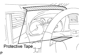
Apply protective tape to the areas shown in the illustration.
-
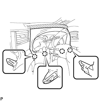
Disengage the 4 claws.
-
Disengage the 7 claws and 2 guides to remove the No. 1 instrument cluster finish panel.
-
-
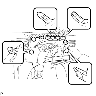
REMOVE COMBINATION METER ASSEMBLY
-
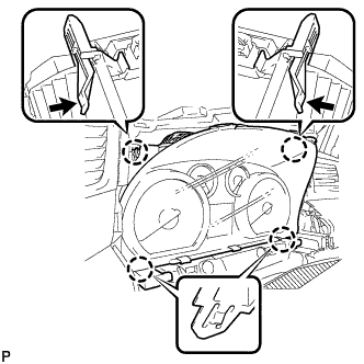
Disengage the 4 claws.
-
Pull the combination meter assembly, disconnect the connector, and remove the combination meter assembly as shown in the illustration.
Note
When removing the combination meter assembly, do not damage the upper instrument panel sub-assembly and combination meter assembly.
-
-
REMOVE NO. 1 INSTRUMENT CLUSTER FINISH PANEL GARNISH
-
Disengage the 4 claws.
-
Disconnect the connector and remove the No. 1 instrument cluster finish panel garnish.
-
-
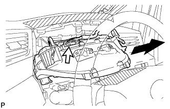
REMOVE NO. 1 INSTRUMENT PANEL UNDER COVER SUB-ASSEMBLY (for RHD)
-

Remove the 2 screws <B>.
-
Disengage the 2 claws and 2 guides.
-
Disengage the 2 claws and disconnect the DLC3.
-
Disengage the clamp.
-
Disconnect each connector and remove the No. 1 instrument panel under cover sub-assembly.
-
-
REMOVE NO. 1 INSTRUMENT PANEL UNDER COVER SUB-ASSEMBLY (for LHD)
-

Remove the 2 screws <B>.
-
Disengage the 2 claws and guide.
-
Disengage the clamp.
-
Disconnect each connector and remove the No. 1 instrument panel under cover sub-assembly.
-
-
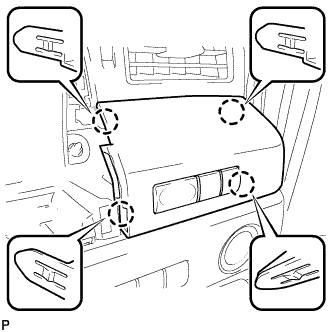
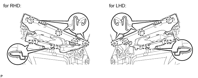
REMOVE LOWER INSTRUMENT PANEL FINISH PANEL (for RHD)
-
Disengage the 3 claws and disconnect the hood lock control cable assembly.
-

Disengage the 3 claws and disconnect the fuel lid lock control cable assembly.
-
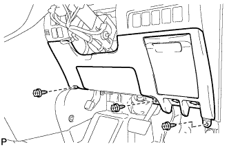
Remove the 3 screws <B>.
-
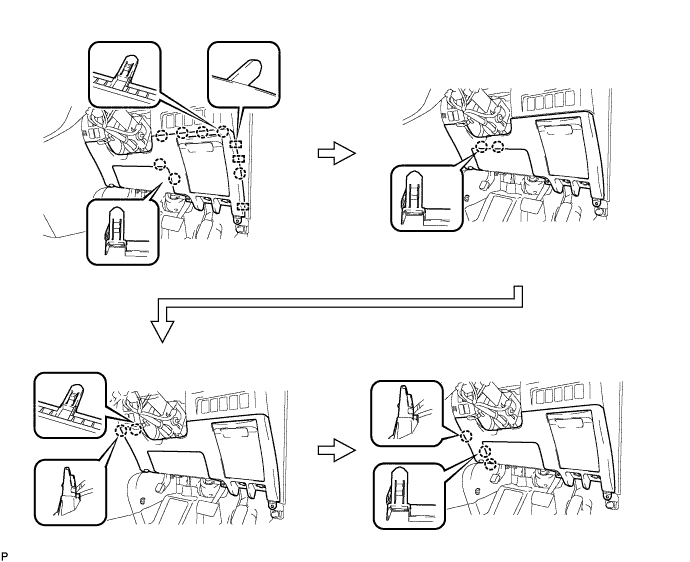
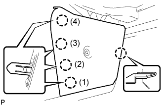
Disengage the 14 claws and the 3 guides, and remove the lower instrument panel finish panel as shown in the illustration.
Note
-
Make sure to follow the order shown in the illustration to avoid damage to the lower instrument panel finish panel.
-
While supporting the knee airbag, remove the lower instrument panel finish panel.
-
-
-
REMOVE LOWER INSTRUMENT PANEL FINISH PANEL (for LHD)
-

Disengage the 3 claws and disconnect the hood lock control cable assembly.
-
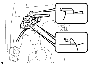
Disengage the 3 claws and disconnect the fuel lid lock control cable assembly.
-

Disconnect the fuel filler opening lid lock sub-assembly and remove the fuel lid lock open lever sub-assembly.
-
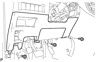
Remove the 3 screws <B>.
-
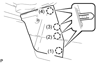
Disengage the 13 claws, clip and the 3 guides and remove the lower instrument panel finish panel as shown in the illustration.
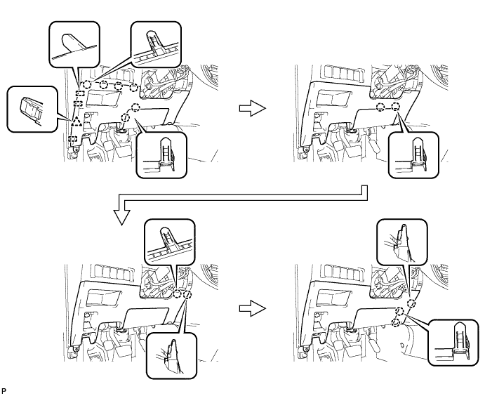
Note
-
Make sure to follow the order shown in the illustration to avoid damage to the lower instrument panel finish panel.
-
While supporting the knee airbag, remove the lower instrument panel finish panel.
-
-
-
REMOVE DRIVER SIDE KNEE AIRBAG ASSEMBLY (for RHD)
-
Check that the engine switch is off.
-
Check that the cable is disconnected from the negative (-) battery terminal.
CAUTION:
Wait at least 90 seconds after disconnecting the cable from the negative (-) battery terminal to disable the SRS system.
-
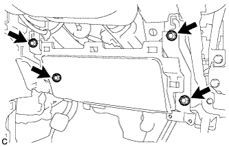
Remove the 4 bolts.
-
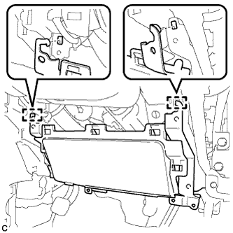
Disengage the 2 hooks and separate the driver side knee airbag assembly.
-
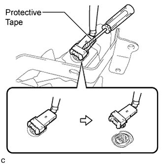
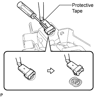
Using a screwdriver with the tip wrapped protective tape, disconnect the connector and remove the driver side knee airbag assembly.
Note
When disconnecting the airbag connector, take care not to damage the airbag wire harness.
-
-
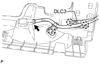
REMOVE DRIVER SIDE KNEE AIRBAG ASSEMBLY (for LHD)
-
Check that the engine switch is off.
-
Check that the cable is disconnected from the negative (-) battery terminal.
CAUTION:
Wait at least 90 seconds after disconnecting the cable from the negative (-) battery terminal to disable the SRS system.
-
Remove the 4 bolts.
-
Disengage the 2 claws to remove the DLC3 from the driver side knee airbag assembly.
-
Disengage the 2 hooks and separate the driver side knee airbag assembly.
-
Using a screwdriver with the tip wrapped protective tape, disconnect the connector and remove the driver side knee airbag assembly.
Note
When disconnecting the airbag connector, take care not to damage the airbag wire harness.
-
-
REMOVE CENTER FLOOR CARPET COVER RH (for RHD)
-
Using a clip remover, remove the 2 clips.
-
Disengage the 4 claws and remove the center floor carpet cover RH in the order shown in the illustration.
Tech Tips
Remove the center floor carpet cover RH while pushing on the instrument cluster finish panel.
-
-
REMOVE CENTER FLOOR CARPET COVER RH (for LHD)
-
Using a clip remover, remove the clip.
-
Disengage the 5 claws and remove the center floor carpet cover RH in the order shown in the illustration.
Tech Tips
Remove the center floor carpet cover RH while pushing on the instrument cluster finish panel.
-
-
REMOVE CENTER FLOOR CARPET COVER LH
-

Using a clip remover, remove the clip.
-
Disengage the 4 claws and remove the center floor carpet cover LH in the order shown in the illustration.
Tech Tips
Remove the center floor carpet cover LH while pushing on the instrument cluster finish panel.
-
-
REMOVE NO. 2 INSTRUMENT PANEL UNDER COVER SUB-ASSEMBLY
-
Disengage the 4 claws and 2 guides.
-
Disconnect the connector and remove the No. 2 instrument panel under cover sub-assembly.
-
-
REMOVE GLOVE COMPARTMENT DOOR ASSEMBLY
-
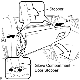
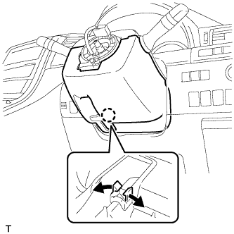
Disengage the claw and release the glove compartment door stopper.
-
Slightly bend stoppers (A) and (B) in the directions indicated by the arrows in the illustration and pull the glove compartment door assembly until the stoppers are released.
-
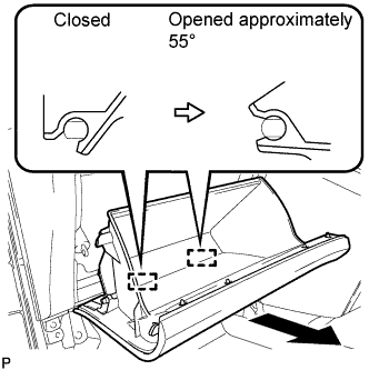
Open the glove compartment door assembly to approximately 55° from its closed position. Pull it horizontally toward the rear of the vehicle to disengage the 2 hinges and remove the glove compartment door assembly.
Note
Pulling the glove compartment door assembly upward to remove it causes the hinges to deform. Be sure to pull out the glove compartment door assembly horizontally.
-
-
REMOVE INSTRUMENT PANEL BOX ASSEMBLY
-
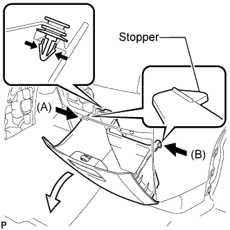
Slightly bend stoppers (A) and (B) in the directions indicated by the arrows in the illustration and pull the instrument panel box assembly until the stoppers are released.
-
Remove the damper clip.
-
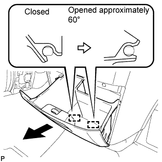
Open the instrument panel box assembly to approximately 60° from its closed position. Pull it horizontally toward the rear of the vehicle to disengage the 2 hinges and remove the instrument panel box assembly.
Note
Pulling the instrument panel box assembly upward to remove it causes the hinges to deform. Be sure to pull out the instrument panel box horizontally.
-
-
REMOVE INSTRUMENT CLUSTER FINISH PANEL ASSEMBLY
-
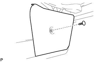
Remove the bolt <C>.
-
Disengage the 12 claws.
Tech Tips
First disengage the 6 claws for the right side and then pull the panel to the rear of the vehicle to disengage the 6 claws for the left side.
-
Disengage the 3 claws.
-
Disconnect each connector and remove the instrument cluster finish panel assembly.
-
-
REMOVE SHIFT LEVER KNOB SUB-ASSEMBLY
-
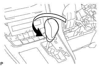
Turn the shift lever knob counterclockwise and remove the shift lever knob sub-assembly.
-
-
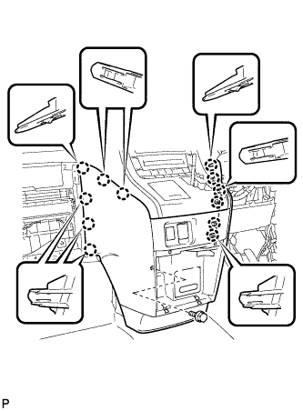
REMOVE CENTER INSTRUMENT CLUSTER FINISH PANEL SUB-ASSEMBLY
-
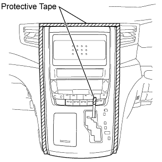
Apply protective tape to the area shown in the illustration.
-
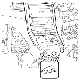
Move the shift lever to N.
-
Disengage the 3 claws as shown in the illustration.
Note
Make sure to disengage the lower claws first. The center instrument cluster finish panel sub-assembly may be damaged if the upper claws are disengaged first.
-
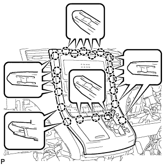
Disengage the 20 claws.
Note
Make sure to disengage the lower claws first. The center instrument cluster finish panel sub-assembly may be damaged if the upper claws are disengaged first.
-
Disconnect the connector and remove the center instrument cluster finish panel sub-assembly.
-
-
REMOVE NO. 2 INSTRUMENT CLUSTER FINISH PANEL GARNISH (for RHD)
-
Disengage the 8 claws and remove the No. 2 instrument cluster finish panel garnish.
Note
Disengage the bottom claws first.
-
-
REMOVE NO. 2 INSTRUMENT CLUSTER FINISH PANEL GARNISH (for LHD)
-
Disengage the 8 claws and remove the No. 2 instrument cluster finish panel garnish.
Note
Disengage the bottom claws first.
-
-
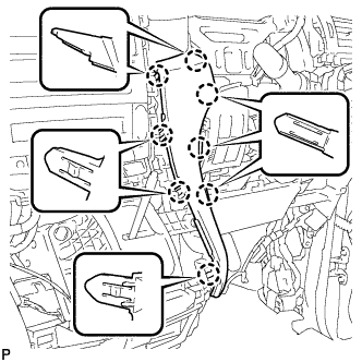
REMOVE NO. 3 INSTRUMENT CLUSTER FINISH PANEL GARNISH
-
Disengage the 16 claws and remove the No. 3 instrument cluster finish panel garnish.
Note
Disengage the bottom claws first.
-
-
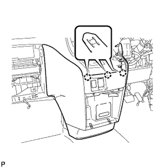
REMOVE NO. 1 INSTRUMENT PANEL BOX DOOR SUB-ASSEMBLY
-
Using a screwdriver, disengage the 6 claws as shown in the illustration.
Tech Tips
Pull the door toward the rear of the vehicle while pushing down on the 4 claws at the corners.
Note
-
When pushing down on the 4 claws, be careful not to damage them. These claws are difficult to disengage.
-
When removing the No. 1 instrument panel box door sub-assembly, make sure to close the lid to avoid damage.
-
-
Disconnect the connector and remove the No. 1 instrument panel box door sub-assembly.
-
-
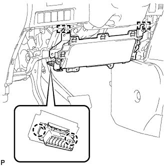
DISCONNECT INSTRUMENT PANEL WIRE ASSEMBLY
-
Check that the engine switch is off.
-
Check that the cable is disconnected from the negative (-) battery terminal.
CAUTION:
Wait at least 90 seconds after disconnecting the cable from the negative (-) battery terminal to disable the SRS system.
-
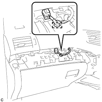
Disengage the wire harness clamp.
-
Disconnect the connector.
Note
When disconnecting the airbag connector, take care not to damage the airbag wire harness.
-
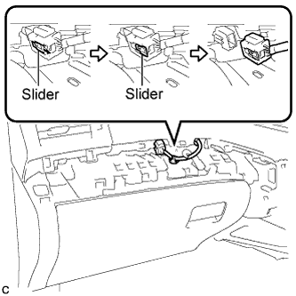
Slide the slider to release the lock, and then disconnect the connector.
-
-
-
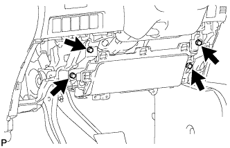
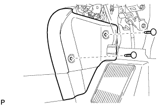
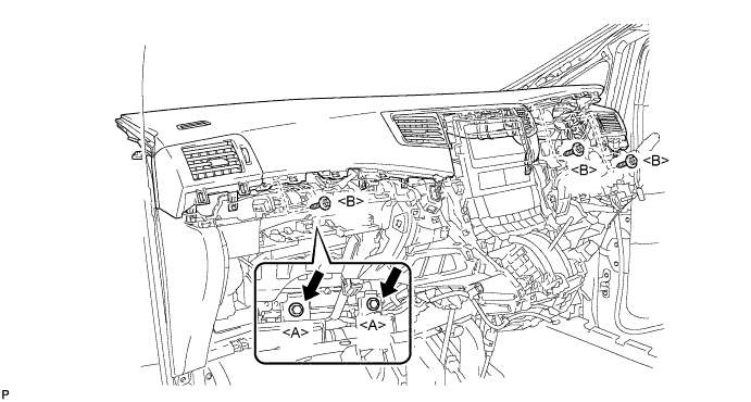
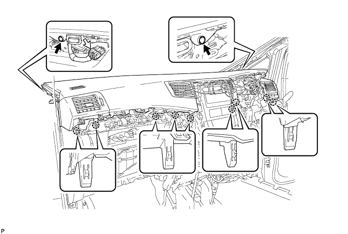
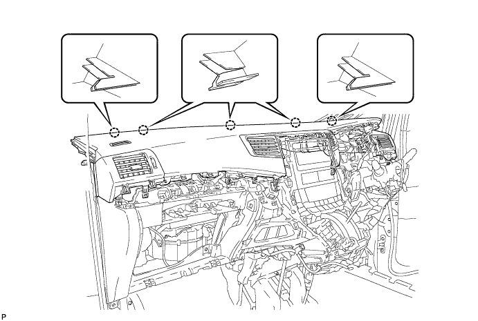
REMOVE UPPER INSTRUMENT PANEL SUB-ASSEMBLY
Tech Tips
It is possible to remove the instrument panel register assembly with the upper instrument panel sub-assembly still installed to the vehicle body. Refer to the disassembly procedure for the upper instrument panel sub-assembly.
-
Remove the 3 screws <B>.
-
Remove the 2 passenger airbag bolts <A>.
-
Using a clip remover, remove the 2 clips.
-
Disconnect the connector.
-
Disengage the 9 claws.
-
Disengage the 5 claws and remove the upper instrument panel sub-assembly.
-
-
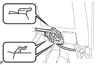
REMOVE POWER STEERING ECU ASSEMBLY
-
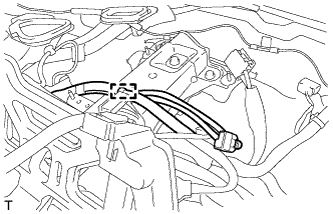
Disconnect the connector from the power steering ECU assembly.
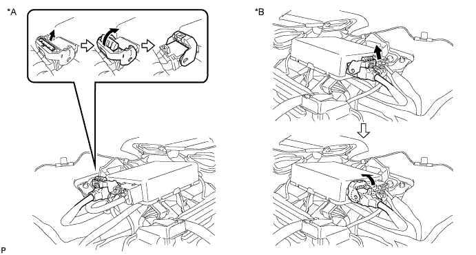
Text in Illustration *A for LHD *B for RHD Tech Tips
Pull out the lock of the lock lever, and then raise the lock lever to disconnect the connector as shown in the illustration.
-
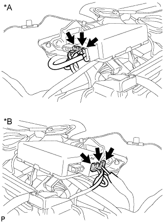
Text in Illustration *A for LHD *B for RHD Disconnect the 3 connectors from the power steering ECU assembly.
-
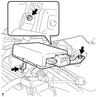
Remove the 3 nuts and power steering ECU assembly.
-
-
REMOVE COLUMN HOLE COVER SILENCER SHEET
-
Remove the 2 clips and column hole cover silencer sheet.
-
-
SEPARATE NO. 2 STEERING INTERMEDIATE SHAFT ASSEMBLY
-
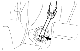
Remove the bolt from the No. 2 steering intermediate shaft assembly.
-
Slide the No. 2 steering intermediate shaft assembly toward the steering column assembly.
Note
Do not separate the No. 2 steering intermediate shaft assembly from the steering intermediate shaft assembly.
-
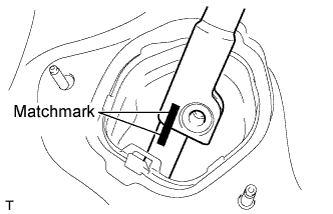
Put matchmarks on the No. 2 steering intermediate shaft assembly and the steering intermediate shaft assembly.
-
Separate the No. 2 steering intermediate shaft assembly from the steering intermediate shaft assembly.
-
-
SEPARATE BRAKE MASTER CYLINDER PUSH ROD CLEVIS
-
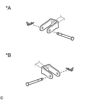
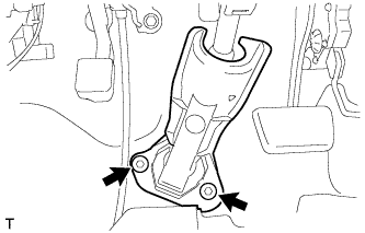
Text in Illustration *A for LHD *B for RHD Remove the clip and brake master cylinder push rod clevis pin and separate the brake master cylinder push rod clevis from the brake pedal support assembly.
-
-
REMOVE STEERING COLUMN ASSEMBLY
-
Disengage the wire harness clamp from the instrument panel reinforcement.
-
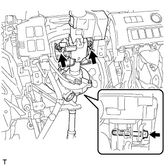
Remove the bolt, 2 nuts and steering column assembly with the No. 2 steering intermediate shaft assembly.
Note
Do not damage the steering column assembly (especially motor and torque sensor). If the steering column assembly is damaged, replace it with a new one.
-