BRAKE PEDAL INSTALLATION

-
INSTALL BRAKE PEDAL SUPPORT ASSEMBLY
-
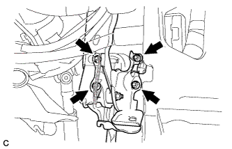
Install the brake pedal support assembly with the 4 nuts.
- Torque:
- 13 N*m { 130 kgf*cm, 9 ft.*lbf }
Note
-
Make sure that the brake pedal support does not interfere with the instrument panel reinforcement.
-
Do not apply excessive force to the brake lines.
Tech Tips
Push out the brake booster assembly toward the engine compartment if necessary.
-
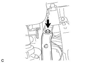
Install the brake pedal support assembly to the instrument panel reinforcement with the bolt.
- Torque:
- 24 N*m { 241 kgf*cm, 17 ft.*lbf }
-
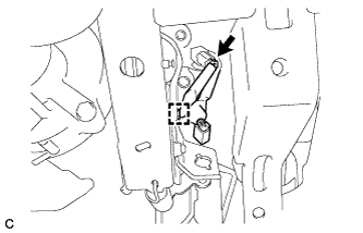
Connect the clamp and connector to the brake pedal support assembly.
-
-
INSTALL STOP LIGHT SWITCH MOUNTING ADJUSTER
-
Engage the 2 claws to install the stop light switch mounting adjuster.
-
-
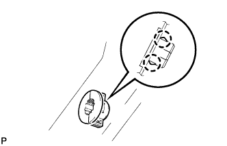
INSTALL STOP LIGHT SWITCH ASSEMBLY
-
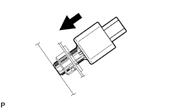
Insert the stop light switch assembly until the rod hits the pedal.
Note
When inserting the stop light switch assembly, support the pedal from behind so that the pedal is not depressed.
-
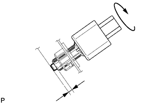
Make a quarter turn clockwise to install the stop light switch assembly.
- Torque:
- 1.5 N*m { 15 kgf*cm, 13 in.*lbf, or less }
Note
When inserting the stop light switch assembly, support the pedal from behind so that the pedal is not depressed.
-
Connect the connector.
-
Check the protrusion of the rod.
Protrusion of the rod 0.5 to 2.6 mm (0.0197 to 0.102 in.) If the protrusion is not as specified, adjust it.
Note
Do not depress the brake pedal.
-
-
CONNECT BRAKE MASTER CYLINDER PUSH ROD CLEVIS
-
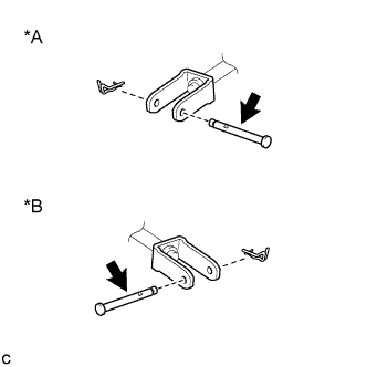
Text in Illustration *A for LHD *B for RHD 
Lithium Soap Base Glycol Grease Apply lithium soap base glycol grease to the contact surface of the brake master cylinder push rod clevis pin.
-
Connect the brake master cylinder push rod clevis to the brake pedal support assembly with the brake master cylinder push rod clevis pin and a new clip.
-
-
INSTALL BRAKE MASTER CYLINDER SUB-ASSEMBLY
Tech Tips
Refer to the instructions for installation of the brake master cylinder sub-assembly Click here.
-
CONNECT CABLE TO NEGATIVE BATTERY TERMINAL
Note
When disconnecting the cable, some systems need to be initialized after the cable is reconnected Click here.
-
INSPECT AND ADJUST BRAKE PEDAL HEIGHT
-
Check the brake pedal height.
-
Turn back the carpet.
-
Measure the brake pedal height.
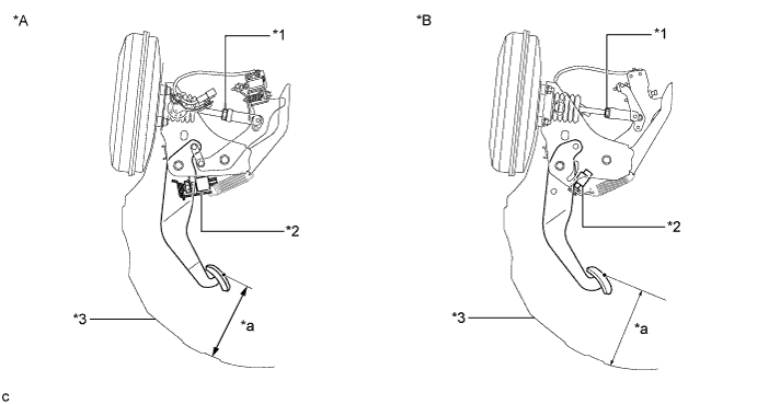
Text in Illustration *A for LHD *B for RHD *1 Clevis Lock Nut *2 Stop Light Switch *3 Dash Panel - - *a Pedal Height - - Standard pedal height (for LHD) 222.1 to 232.1 mm (8.74 to 9.13 in.) Standard pedal height (for RHD) 215.9 to 225.9 mm (8.50 to 8.89 in.)
-
-
Adjust the brake pedal height.
-
Remove the stop light switch assembly Click here.
-
Loosen the brake master cylinder push rod clevis lock nut.
-
Adjust the brake pedal height by turning the push rod.
-
Tighten the brake master cylinder push rod clevis lock nut.
- Torque:
- 26 N*m { 265 kgf*cm, 19 ft.*lbf }
-
Install the stop light switch assembly Click here.
-
Check that the stop lights do not come on when the brake pedal is released.
-
-
-
INSPECT BRAKE PEDAL FREE PLAY
-
Stop the engine and firmly depress the brake pedal several times until no vacuum is left in the booster.
-
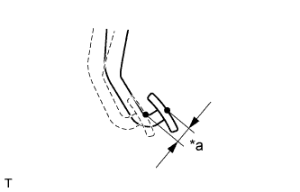
Text in Illustration *a Brake Pedal Free Play Measure the free play of the brake pedal.
Standard pedal free play 1.0 to 6.0 mm (0.0394 to 0.236 in.) If the pedal free play is not as specified, check the stop light switch clearance Click here. If the pedal free play is as specified, proceed to the Inspect Brake Pedal Reserve Distance procedure.
-
-
INSPECT BRAKE PEDAL RESERVE DISTANCE
Tech Tips
Measure the distance at the same point used for the brake pedal height inspection.
-
Start the engine.
-
Depress the brake pedal and check the pedal reserve distance.
-
Depress the brake pedal with a force of 490 N (50 kgf, 110 lbf).
-
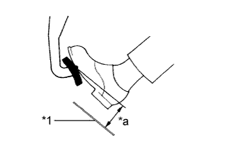
Text in Illustration *1 Dash Panel *a Pedal Reserve Distance Measure the distance between the brake pedal and dash panel shown in the illustration.
Standard pedal reserve distance 124 mm (4.88 in.) If the distance is not as specified, troubleshoot the brake system Click here.
-
-
-
DISCONNECT CABLE TO NEGATIVE BATTERY TERMINAL
CAUTION:
Wait for 90 seconds after disconnecting the cable to prevent the airbag working.
Note
When disconnecting the cable, some systems need to be initialized after the cable is reconnected Click here.
-
INSTALL DRIVER SIDE KNEE AIRBAG ASSEMBLY
Tech Tips
Refer to the instructions for installation of the driver side knee airbag assembly Click here.