FRONT SPEED SENSOR INSTALLATION

Tech Tips
-
Use the same procedure for the RH side and LH side.
-
The procedure listed below is for the LH side.
-
If the sensor rotor needs to be replaced, replace it together with the front axle hub sub-assembly.
-
INSTALL FRONT SPEED SENSOR
-
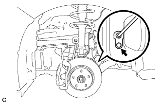
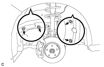
Install the front speed sensor with the bolt.
- Torque:
- 8.5 N*m { 87 kgf*cm, 75 in.*lbf }
Note
-
Prevent foreign matter from attaching to the sensor tip.
-
Do not file the hole or contact surface because the gap between the magnet rotor and front speed sensor is important.
-
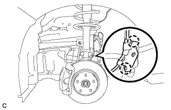
Temporarily install the No. 1 sensor clamp and front brake flexible hose to the shock absorber.
Note
-
Do not twist the wire harness for the front speed sensor when installing it.
-
Tighten the brake flexible hose and front speed sensor together with the bolt. Make sure that the front brake flexible hose is positioned over the front speed sensor.
-
-
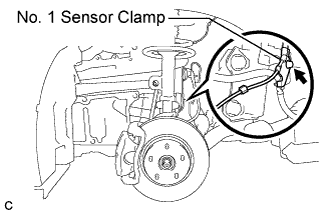
Fully tighten the front brake flexible hose and No. 1 sensor clamp with the bolt.
- Torque:
- 19 N*m { 189 kgf*cm, 14 ft.*lbf }
-
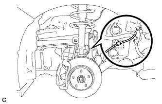
Install the clamp to the shock absorber.
-
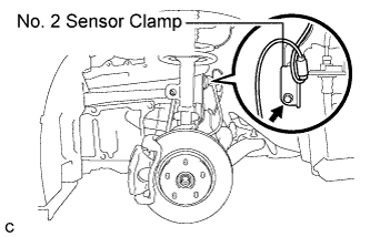
Install the No. 2 sensor clamp to the body with the bolt.
- Torque:
- 8.5 N*m { 87 kgf*cm, 75 in.*lbf }
-
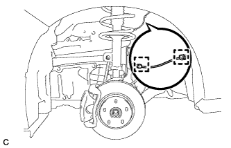
Install the 2 front speed sensor wire harness clamps to the body.
-
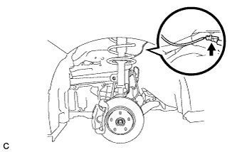
Connect the front speed sensor connector.
-
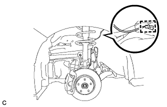
Install the front speed sensor wire harness clamp to the body.
-
Install the fender liner with the 4 screws.
-
-
INSTALL FRONT WHEEL
- Torque:
- 103 N*m { 1050 kgf*cm, 76 ft.*lbf }
-
CONNECT CABLE TO NEGATIVE BATTERY TERMINAL
Note
When disconnecting the cable, some systems need to be initialized after the cable is reconnected Click here.
-
CHECK FOR SPEED SENSOR SIGNAL
-
Check for the speed sensor signal Click here.
-