BRAKE ACTUATOR INSTALLATION

-
INSTALL BRAKE ACTUATOR ASSEMBLY
-
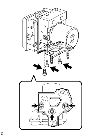
Using a hexagon wrench (5 mm), install the No. 2 brake actuator bracket to the brake actuator assembly with the 3 bolts.
- Torque:
- 5.5 N*m { 56 kgf*cm, 49 in.*lbf }
Note
-
Do not remove the hole plugs of a new brake actuator before connecting the 6 brake lines because the brake actuator assembly is filled with brake fluid.
-
Do not hold the actuator by the connector.
-
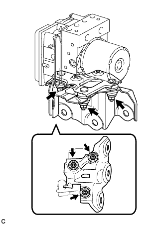
Install the brake actuator bracket assembly to the brake actuator assembly with No. 2 brake actuator bracket with the 3 nuts.
- Torque:
- 8.0 N*m { 82 kgf*cm, 71 in.*lbf }
-
-
INSTALL BRAKE ACTUATOR ASSEMBLY WITH BRACKET
-
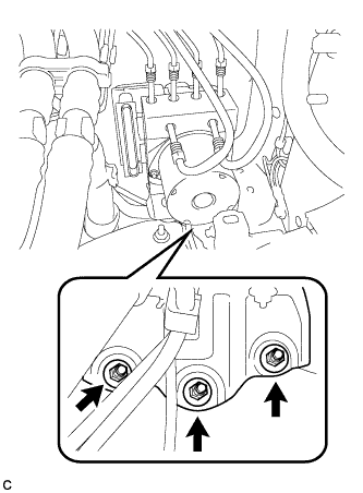
Install the brake actuator assembly with bracket to the body with 3 nuts.
- Torque:
- 19 N*m { 194 kgf*cm, 14 ft.*lbf }
Note
Do not damage the brake lines or wire harness.
-
Install the brake line clamp to the brake actuator bracket assembly.
-
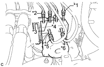
Temporarily tighten each brake line to the correct positions of the brake actuator assembly with bracket as shown in the illustration.
Tech Tips
-
*1: To front wheel cylinder RH
-
*2: To front wheel cylinder LH
-
*3: To rear wheel cylinder RH
-
*4: To rear wheel cylinder LH
-
*5: From 2nd of master cylinder
-
*6: From 1st of master cylinder
-
-
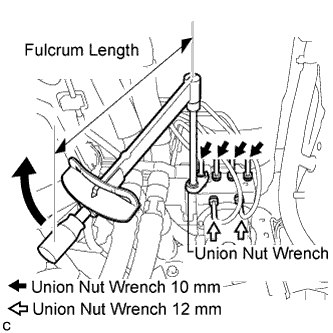
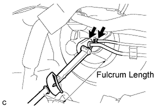
Using a union nut wrench (10 mm) and a union nut wrench (12 mm), fully tighten each brake line.
- Torque:
- Flare nut (M10) without a union nut wrench (10 mm)
- 15 N*m { 155 kgf*cm, 11 ft.*lbf }
- Flare nut (M10) with a union nut wrench (10 mm)
- 14 N*m { 143 kgf*cm, 10 ft.*lbf }
- Flare nut (M12) without a union nut wrench (12mm)
- 20 N*m { 199 kgf*cm, 15 ft.*lbf }
- Flare nut (M12) with a union nut wrench (12mm)
- 17 N*m { 177 kgf*cm, 13 ft.*lbf }
Note
-
Use a torque wrench with a fulcrum length of 250 mm (9.84 in.).
-
This torque value is effective when the union nut wrench is parallel to the torque wrench.
-
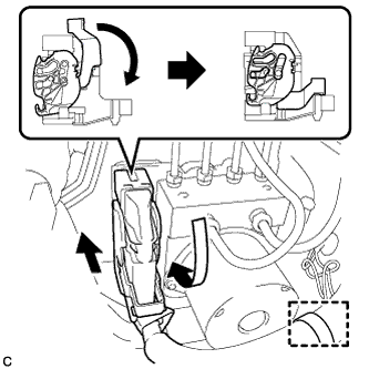
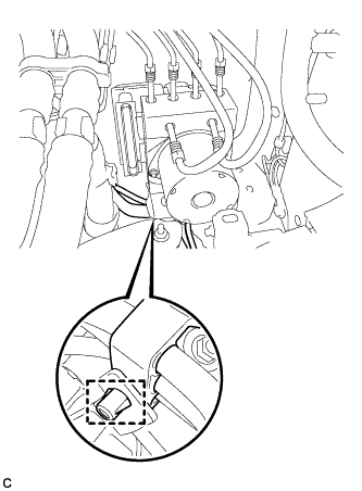
Connect the brake actuator connector and install the clamp.
Note
Make sure that the connector is locked securely.
-
-
INSTALL ENGINE UNDER COVER NO.2 (for 2AZ-FE)
-
INSTALL AIR CLEANER CASE (for 2AZ-FE)
-
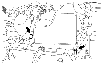
Install the air cleaner case with the 3 bolts.
- Torque:
- 7.0 N*m { 71 kgf*cm, 62 in.*lbf }
-
Install the engine wire clamp to the air cleaner case.
-
Install the air cleaner filter element.
-
-
INSTALL AIR CLEANER CASE (for 2GR-FE)
-
Install the air cleaner case with the 3 bolts.
- Torque:
- 7.0 N*m { 71 kgf*cm, 62 in.*lbf }
-
Connect the wire clamp.
-
Install the air cleaner filter element.
-
-
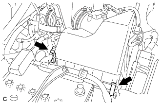
INSTALL AIR CLEANER CAP SUB-ASSEMBLY (for 2AZ-FE)
-
Install the air cleaner cap sub-assembly with hose and lock the 2 clamps.
-
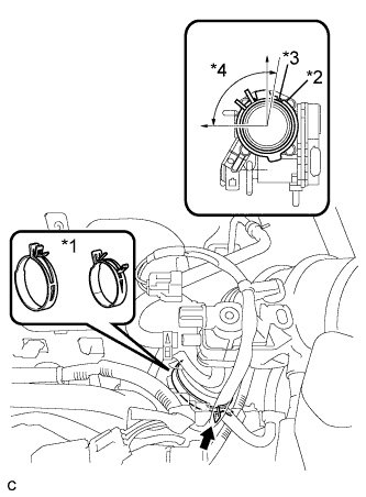
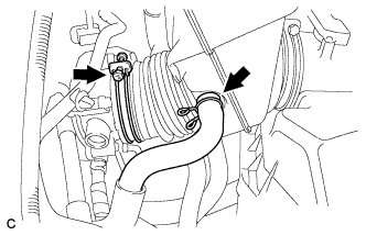
Text in Illustration *1 No. 1 air cleaner hose clamp *2 Groove *3 Tab *4 95° Connect the No. 1 air cleaner hose to the throttle body and release the lock of the No. 1 air cleaner hose clamp.
Note
-
Align the groove of the air cleaner hose with the tab of the throttle body and install the hose.
-
Make sure that the tab of the No. 1 air cleaner hose clamp stays within the range shown by *4
-
-
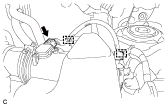
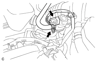
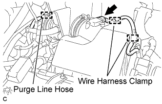
Connect the 2 wire harness clamps and the mass air flow meter connector.
-
Connect the ventilation hose.
-
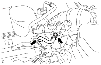
Connect the purge line hose to the No. 1 vacuum switching valve assembly and air cleaner hose.
-
Connect the fuel vapor feed hose to the No. 1 vacuum switching valve assembly.
-
Connect the wire harness clamp and No. 1 vacuum switching valve connector.
-
-
INSTALL AIR CLEANER CAP SUB-ASSEMBLY (for 2GR-FE)
-
Install the air cleaner cap sub-assembly to the air cleaner case with the 2 clamps.
-
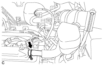
Connect the air cleaner hose to the throttle body with the hose clamp.
-
Connect the ventilation hose.
-
Connect the purge line hose.
-
Connect the 2 wire harness clamps and mass air flow meter connector.
-
-
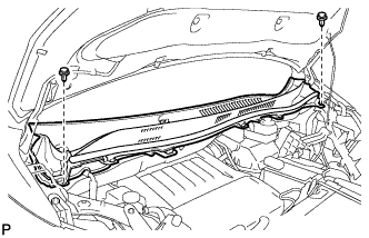
INSTALL OUTER COWL TOP PANEL
-
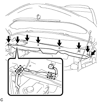
Install the outer cowl top panel with the 8 bolts.
- Torque:
- 8.8 N*m { 90 kgf*cm, 78 in.*lbf }
-
Connect the 2 clamps to the outer cowl top panel.
-
Remove the protective tape.
-
-
INSTALL BRAKE MASTER CYLINDER RESERVOIR WITH BRACKET
-
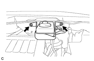
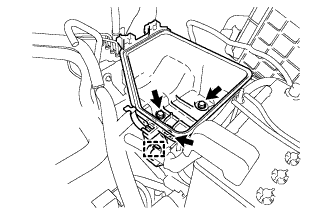
Install the brake master cylinder reservoir with bracket to the outer cowl top panel with the 2 nuts.
- Torque:
- 6.5 N*m { 66 kgf*cm, 58 in.*lbf }
-
-
INSTALL WINDSHIELD WIPER MOTOR AND LINK ASSEMBLY
-
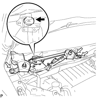
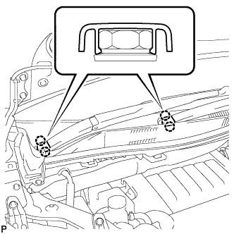
Install the windshield wiper motor and link assembly with the 3 bolts as shown in the illustration.
- Torque:
- 5.5 N*m { 56 kgf*cm, 49 in.*lbf }
-
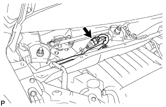
Connect the connector.
-
-
INSTALL COWL TOP VENTILATOR LOUVER SUB-ASSEMBLY
-
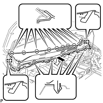
Engage the 15 claws and 2 guides to install the cowl top ventilator louver sub-assembly as shown in the illustration.
-
Install the 2 clips.
-
-
INSTALL FRONT WIPER ARM AND BLADE ASSEMBLY LH
-
When reusing the front wiper arm and blade assembly LH:
-
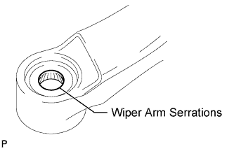
Clean the wiper arm serrations.
-
-
When reusing the windshield wiper link assembly:
-
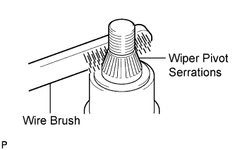
Clean the wiper pivot serrations with a wire brush.
-
-
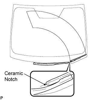
Install the front wiper arm and blade assembly LH with the nut to the position shown in the illustration.
- Torque:
- 24 N*m { 245 kgf*cm, 18 ft.*lbf }
-
Operate the front wipers while spraying washer fluid onto the windshield. Make sure that the front wipers function properly and the wipers do not come into contact with the vehicle body.
-
-
INSTALL FRONT WIPER ARM AND BLADE ASSEMBLY RH
-
Operate the wiper and stop the windshield wiper motor at the automatic stop position.
-
When reusing the front wiper arm and blade assembly RH:
-
Clean the wiper arm serrations.
-
-
When reusing the windshield wiper link assembly:
-
Clean the wiper pivot serrations with a wire brush.
-
-
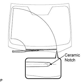
Install the front wiper arm and blade assembly RH with the nut to the position shown in the illustration.
- Torque:
- 24 N*m { 245 kgf*cm, 18 ft.*lbf }
-
-
INSTALL WINDSHIELD WIPER ARM COVER
-
Engage the 2 claws to install the 2 windshield wiper arm covers.
-
-
INSTALL V-BANK COVER SUB-ASSEMBLY
-
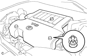
Fit the 3 retainers and install the V-bank cover sub-assembly.
-
-
FILL RESERVOIR WITH BRAKE FLUID
-
Fill the reservoir with brake fluid.
Brake Fluid SAE J1703 or FMVSS No. 116 DOT 3 Note
Before replacing the brake fluid or bleeding the brake system, confirm that the reservoir located above the master cylinder assembly is filled with brake fluid.
-
-
BLEED BRAKE MASTER CYLINDER
Tech Tips
If the master cylinder is reinstalled or runs out of brake fluid, bleed the master cylinder.
Note
-
If the master cylinder is reinstalled or runs out of brake fluid, bleed the master cylinder.
-
To prevent brake fluid from damaging painted surface, cover any surrounding parts with a piece of cloth.
-
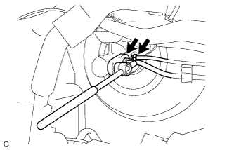
Using a union nut wrench (12 mm), disconnect the 2 brake tubes from the brake master cylinder assembly.
-
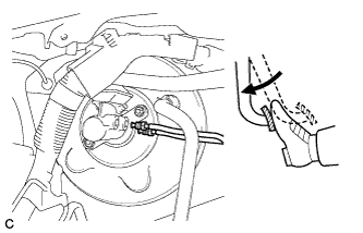
Slowly depress the brake pedal and hold it down.
-
Cover the 2 tube holes with your fingers and release the brake pedal.
-
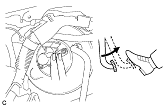
Uncover the holes, slowly depress the brake pedal and hold it down. While holding down the brake pedal, cover the tube holes again. Repeat this step 3 or 4 times.
-
Using a union nut wrench (12 mm), connect the 2 brake tubes to the brake master cylinder assembly.
- Torque:
- without a union nut wrench
- 20 N*m { 199 kgf*cm, 14 ft.*lbf }
- with a union nut wrench
- 18 N*m { 183 kgf*cm, 13 ft.*lbf }
Note
-
Use a torque wrench with a fulcrum length of 250 mm (9.84 in.).
-
This torque value is effective when the union nut wrench is parallel to the torque wrench.
-
-
BLEED BRAKE LINE
Note
-
Bleed the brake line of the wheel farthest from the master cylinder first.
-
To prevent air from entering the brake lines, bleed the brake lines while keeping the reservoir filled to the MAX line with brake fluid.
-
Connect a vinyl tube to the bleeder plug.
-
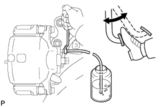
Depress the brake pedal several times, and while holding down the brake pedal, loosen the bleeder plug*1.
-
When fluid stops coming out, tighten the bleeder plug and release the brake pedal*2.
-
Repeat steps *1 and *2 until all the air in the fluid is completely bled out.
- Torque:
- Front disc brake bleeder plug
- 8.3 N*m { 85 kgf*cm, 74 in.*lbf }
- Rear disc brake bleeder plug
- 10 N*m { 102 kgf*cm, 7 ft.*lbf }
-
Repeat the above steps to bleed the brake lines for each wheel.
-
-
INSPECT BRAKE FLUID LEVEL
-
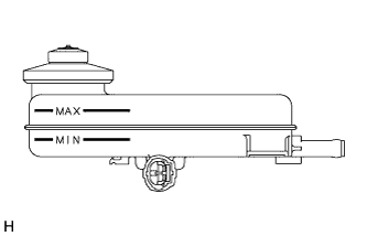
Check the fluid level.
Tech Tips
If brake fluid level is lower than the MIN line, check for leaks and inspect the disc brake pads. If necessary, refill the reservoir with brake fluid to the MAX line after repair or replacement.
Brake Fluid SAE J1703 or FMVSS No. 116 DOT 3
-
-
INSPECT FOR BRAKE FLUID LEAK
-
CONNECT CABLE TO NEGATIVE BATTERY TERMINAL
Note
When disconnecting the cable, some systems need to be initialized after the cable is reconnected Click here.
-
INSPECT BRAKE ACTUATOR ASSEMBLY WITH INTELLIGENT TESTER
Tech Tips
-
CHECK AND CLEAR DTC
Tech Tips