REAR AXLE BEAM INSTALLATION

-
INSTALL REAR AXLE CARRIER BUSHING LH
-
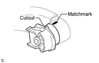
Align the cutout of a new rear axle carrier bushing LH and the matchmark on the rear axle beam assembly and then temporarily install the rear axle carrier bushing LH to the rear axle beam assembly. (Perform this step when reusing the rear axle beam assembly.)
Note
-
Do not apply grease to the rear axle carrier bushing LH or rear axle beam assembly.
-
Install the rear axle carrier bushing LH in the same direction as the removed bushing.
-
-
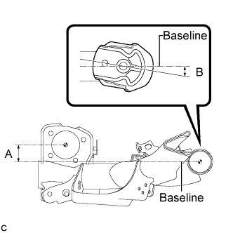
Temporarily install a new rear axle carrier bushing LH to the position as shown in the illustration. (Perform this step when installing a new rear axle beam assembly.)
Standard (A) 47.5 mm (1.87 in.) Standard (B) 3°35' to 9°35' (3.6° to 9.6°) Note
-
Do not apply grease to the rear axle carrier bushing LH or rear axle beam assembly.
-
Install the rear axle carrier bushing LH in the same direction as the removed bushing.
-
-
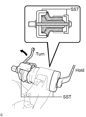
Using SST, install the rear axle carrier bushing LH to the rear axle beam assembly.
- SST
- 09710-28031 ( 09711-02010, 09711-02020, 09711-02030, 09711-02040, 94622-51200 )
Note
-
Apply a small amount of grease to the threads and tip of SST (center bolt) before use.
-
Apply a small amount of grease to the threads and tip of SST (2 washers) before use.
-
Be careful not to damage the rubber part of the rear axle carrier bushing when installing it.
-
Do not deform the rear axle carrier bushing rib.
-
Do not apply grease to the rear axle carrier bushing LH or rear axle beam assembly.
-
-
INSTALL REAR AXLE CARRIER BUSHING RH
Tech Tips
Perform the same procedure as the LH side.
-
TEMPORARILY TIGHTEN REAR AXLE BEAM ASSEMBLY
-
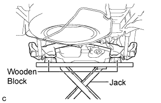
Using wooden blocks and a jack as shown in the illustration, jack up the rear axle beam assembly to allow it to be installed.
Note
Make sure to secure the rear axle beam assembly to prevent it from dropping.
-
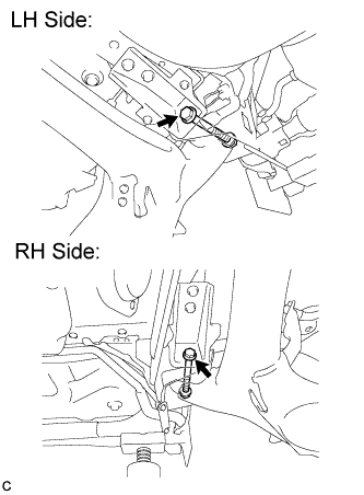
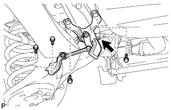
Temporarily install the rear axle beam assembly to the body with the 2 bolts and 2 nuts.
Note
-
Insert the bolts with the threaded ends facing the outside of the vehicle.
-
Since stopper nuts are used, tighten the bolts.
Tech Tips
Fully tighten the nuts and bolts after stabilizing the suspension.
-
-
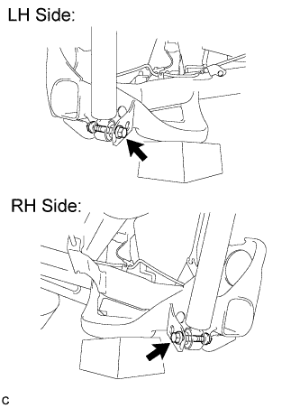
Temporarily install the rear axle beam assembly to the rear shock absorber assembly with the 2 bolts and 2 nuts.
Note
-
Insert the bolts with the threaded ends facing the outside of the vehicle.
-
Since stopper nuts are used, tighten the bolts.
Tech Tips
Fully tighten the nuts and bolts after stabilizing the suspension.
-
-
-
INSTALL REAR AXLE HUB AND BEARING ASSEMBLY LH
-
Temporarily install the parking brake assembly LH with the No. 3 parking brake cable assembly to the vehicle.
-
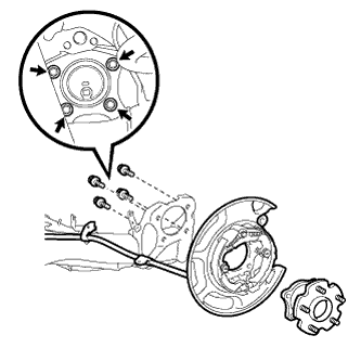
Install the rear axle hub, bearing assembly LH and parking brake assembly LH to the rear axle beam assembly with the 4 bolts.
- Torque:
- 90 N*m { 918 kgf*cm, 66 ft.*lbf }
Note
Make sure that there is no dirt or foreign matter in the bolt threads or on mating surfaces.
-
-
INSTALL REAR AXLE HUB AND BEARING ASSEMBLY RH
Tech Tips
Perform the same procedure as the LH side.
-
INSTALL NO. 2 PARKING BRAKE CABLE ASSEMBLY
-
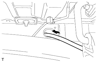
Install the No. 2 parking brake cable assembly to the body through the body hole.
-
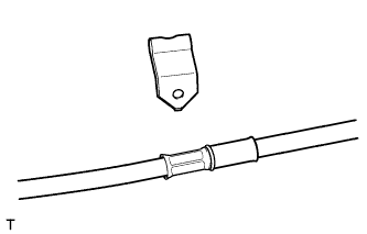
Install the No. 1 parking brake cable clamp to the No. 2 parking brake cable assembly.
-
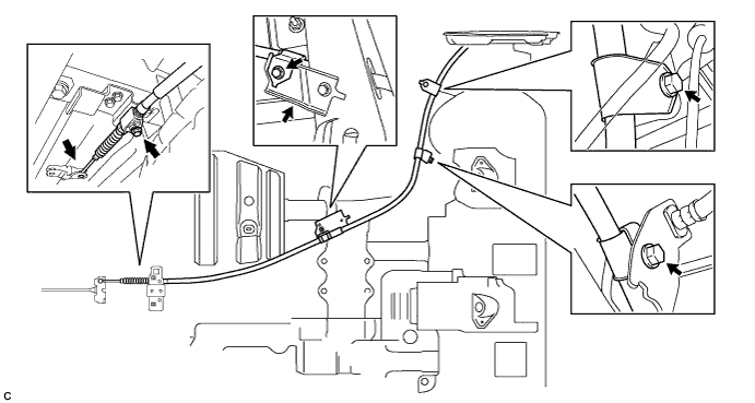
Connect the No. 2 parking brake cable assembly to the parking brake equalizer.
-
Install the No. 2 parking brake cable assembly to the body with the 4 bolts.
- Torque:
- 8.0 N*m { 82 kgf*cm, 71 in.*lbf }
-
-
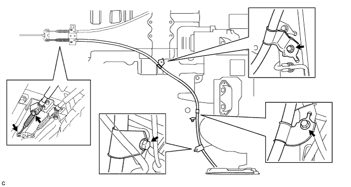
INSTALL NO. 3 PARKING BRAKE CABLE ASSEMBLY
-
Connect the No. 3 parking brake cable assembly to the parking brake equalizer.
-
Install the No. 3 parking brake cable assembly to the body with the 4 bolts.
- Torque:
- 8.0 N*m { 82 kgf*cm, 71 in.*lbf }
-
-
INSTALL REAR NO. 4 BRAKE TUBE
-
Connect the rear No. 4 brake tube to the rear brake tube flexible hose.
Note
-
Do not kink or damage the brake line.
-
Do not allow any foreign matter such as dirt and dust to enter the brake line.
-
-
Install the rear brake tube flexible hose with a new clip.
Note
Install the clip as far as it will go.
-
Install the rear No. 4 brake tube to the rear axle beam assembly with the bolt and nut.
- Torque:
- 8.0 N*m { 82 kgf*cm, 71 in.*lbf }
-
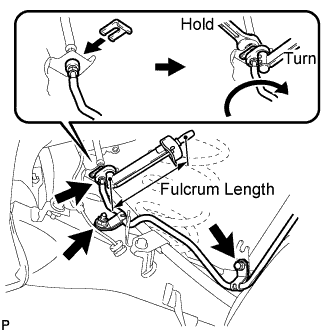
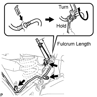
Using a union nut wrench (10 mm), fully tighten the rear No. 4 brake tube to the rear brake tube flexible hose while holding the rear brake tube flexible hose with a wrench.
- Torque:
- without a union nut wrench
- 15 N*m { 155 kgf*cm, 11 ft.*lbf }
- with a union nut wrench
- 14 N*m { 143 kgf*cm, 10 ft.*lbf }
Note
-
Do not kink or damage the brake line.
-
Do not allow any foreign matter such as dirt and dust to enter the brake line.
-
Use a torque wrench with a fulcrum length of 250 mm (9.84 in.).
-
This torque value is effective when the union nut wrench is parallel to the torque wrench.
-
-
INSTALL REAR NO. 3 BRAKE TUBE
-
Connect the rear No. 3 brake tube to the rear brake tube flexible hose.
Note
-
Do not kink or damage the brake line.
-
Do not allow any foreign matter such as dirt and dust to enter the brake line.
-
-
Install the rear brake tube flexible hose with a new clip.
Note
Install the clip as far as it will go.
-
Install the rear No. 3 brake tube to the rear axle beam assembly with the bolt and nut.
- Torque:
- 8.0 N*m { 82 kgf*cm, 71 in.*lbf }
-
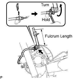
Using a union nut wrench (10 mm), fully tighten the rear No. 4 brake tube to the rear brake tube flexible hose while holding the rear brake tube flexible hose with a wrench.
- Torque:
- without a union nut wrench
- 15 N*m { 155 kgf*cm, 11 ft.*lbf }
- with a union nut wrench
- 14 N*m { 143 kgf*cm, 10 ft.*lbf }
Note
-
Do not kink or damage the brake line.
-
Do not allow any foreign matter such as dirt and dust to enter the brake line.
-
Use a torque wrench with a fulcrum length of 250 mm (9.84 in.).
-
This torque value is effective when the union nut wrench is parallel to the torque wrench.
-
-
INSTALL REAR DISC
-
Install the 2 rear discs Click here.
-
-
INSTALL PARKING BRAKE SHOE ADJUSTING HOLE PLUG
-
Install the 2 parking brake shoe adjusting hole plugs to the 2 rear discs.
-
-
INSTALL REAR DISC BRAKE CALIPER ASSEMBLY LH
-
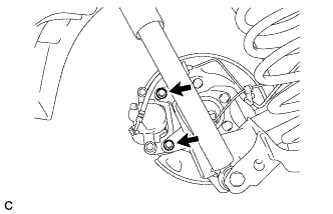
Install the rear disc brake caliper assembly with rear flexible hose LH with the 2 bolts.
-
Connect the rear No. 4 brake tube to the rear flexible hose LH.
Note
-
Do not kink or damage the brake line.
-
Do not allow any foreign matter such as dirt and dust to enter the brake line.
-
-
Install the rear flexible hose LH to the backing plate with a new clip.
Note
Install the clip as far as it will go.
-
Using a union nut wrench (10 mm), fully tighten the rear No. 4 brake tube to the rear flexible hose LH while holding the rear flexible hose LH with a wrench.
- Torque:
- without a union nut wrench
- 15 N*m { 155 kgf*cm, 11 ft.*lbf }
- with a union nut wrench
- 14 N*m { 143 kgf*cm, 10 ft.*lbf }
Note
-
Do not kink or damage the brake line.
-
Do not allow any foreign matter such as dirt and dust to enter the brake line.
-
Use a torque wrench with a fulcrum length of 250 mm (9.84 in.).
-
This torque value is effective when the union nut wrench is parallel to the torque wrench.
-
-
INSTALL REAR DISC BRAKE CALIPER ASSEMBLY RH
Tech Tips
Perform the same procedure as the LH side.
-
INSTALL REAR LOWER COIL SPRING INSULATOR LH
-
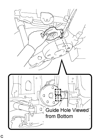
Align the 2 protrusions to the guide holes and install the rear lower coil spring insulator.
Note
Make sure to insert the 2 protrusions fully into the guide holes.
-
-
INSTALL REAR LOWER COIL SPRING INSULATOR RH
Tech Tips
Perform the same procedure as the LH side.
-
INSTALL REAR COIL SPRING LH
-
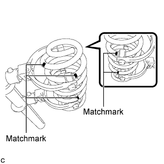
Align the matchmarks on the rear coil spring with the SST hooks and install SST to the rear coil spring as shown in the illustration.
- SST
- 09727-30021
Tech Tips
When installing a new coil spring, adjust the SST installation position by using the matchmarks on the original spring as a reference.
-
Using SST, compress the rear coil spring.
- SST
- 09727-30021
Note
Do not use an impact wrench. It will damage SST.
-
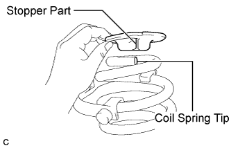
Align the stopper part of the rear upper coil spring insulator with the rear coil spring tip, and install the rear upper coil spring insulator to the rear coil spring.
-
Confirm that the rear upper coil spring insulator and the rear lower coil spring insulator are installed securely before installing the rear coil spring.
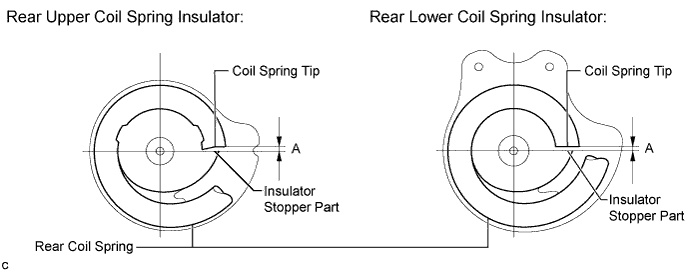
Clearance (A) 10 mm (0.393 in.) or less Tech Tips
If it is difficult to align the rear upper coil spring insulator, a minimal amount of lithium soap base glycol grease may be applied to the insulator.
-
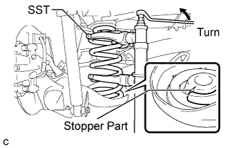
Align the stopper part of the rear lower coil spring insulator with the rear coil spring tip, and temporarily install the rear coil spring with SST to the vehicle.
-
Release SST and install the rear coil spring to the vehicle.
- SST
- 09727-30021
Note
-
Do not use an impact wrench. It will damage SST.
-
Make sure that the rear upper coil spring insulator and rear lower coil spring insulator are correctly aligned and do not fall out of position when installing the spring.
-
Remove SST from the rear coil spring.
- SST
- 09727-30021
-
-
INSTALL REAR COIL SPRING RH
Tech Tips
Perform the same procedure as the LH side.
-
INSTALL REAR SPEED SENSOR WIRE (for LH Side)
-
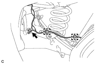
Install the rear speed sensor wire LH to the rear axle beam assembly with the bolt and 2 clamps.
- Torque:
- 8.5 N*m { 87 kgf*cm, 75 in.*lbf }
Note
Do not twist the rear speed sensor wire.
-
Connect the rear speed sensor wire to the rear axle hub and bearing assembly LH.
Note
Do not twist the rear speed sensor wire.
-
-
INSTALL REAR SPEED SENSOR WIRE (for RH Side)
Tech Tips
Perform the same procedure as the LH side.
-
ADJUST PARKING BRAKE
Tech Tips
Refer to the instructions for adjust parking brake Click here.
-
BLEED BRAKE SYSTEM
Tech Tips
Refer to the instructions for bleed brake line Click here.
-
INSTALL TAIL EXHAUST PIPE ASSEMBLY
for 2AZ-FE: Click here
for 2GR-FE: Click here
-
INSPECT FOR EXHAUST GAS LEAK
-
STABILIZE SUSPENSION
-
Install the rear wheels.
- Torque:
- 103 N*m { 1050 kgf*cm, 76 ft.*lbf }
-
Lower the vehicle.
-
Bounce the vehicle up and down several times to stabilize the suspension.
-
Remove the rear wheels.
-
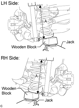
Jack up the spring cup of the rear axle beam assembly, placing a wooden block underneath to avoid damage. Apply load to the suspension so that the rear shock absorber assembly is positioned as shown in the illustration.
Length A 214 mm (8.43 in.) If the rear shock absorber assembly cannot be positioned as shown in the illustration even when the rear axle beam assembly is jacked up, apply additional load to the vehicle such as by having a person sit in the rear seat.
CAUTION:
Do not jack up the rear axle beam assembly too high as the vehicle may fall.
Note
-
When using a jack, make sure that the wooden block does not contact the protrusions of the rear lower coil spring insulator.
-
Make sure to jack up both sides of the rear axle beam assembly evenly to prevent it from twisting.
-
-
-
FULLY TIGHTEN REAR AXLE BEAM ASSEMBLY
-
Fully tighten the 2 bolts on the rear axle beam assembly.
- Torque:
- 135 N*m { 1377 kgf*cm, 100 ft.*lbf }
Note
-
Since stopper nuts are used, tighten the bolts.
-
The final torque must be applied under standard vehicle height conditions.
-
-
FULLY TIGHTEN REAR SHOCK ABSORBER ASSEMBLY LH
-
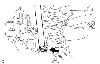
Fully tighten the bolt on the rear shock absorber assembly (lower side).
- Torque:
- 58 N*m { 591 kgf*cm, 43 ft.*lbf }
Note
-
Since a stopper nut is used, tighten the bolt.
-
The final torque must be applied under standard vehicle height conditions.
-
-
FULLY TIGHTEN REAR SHOCK ABSORBER ASSEMBLY RH
Tech Tips
Perform the same procedure as the LH side.
-
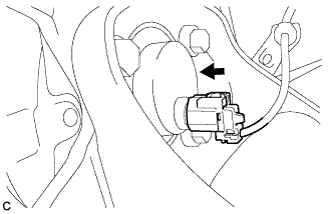
INSTALL REAR HEIGHT CONTROL SENSOR SUB-ASSEMBLY
-
Install the rear height control sensor sub-assembly with the 4 bolts.
- Torque:
- 8.0 N*m { 82 kgf*cm, 71 in.*lbf }
-
Connect the connector.
-
-
INSTALL REAR WHEELS
- Torque:
- 103 N*m { 1050 kgf*cm, 76 ft.*lbf }
-
INSPECT REAR WHEEL ALIGNMENT
-
Inspect the rear wheel alignment Click here.
-
-
PLACE FRONT WHEELS FACING STRAIGHT AHEAD
-
DISCONNECT CABLE FROM NEGATIVE BATTERY TERMINAL
Note
Disconnect the cable from the negative (-) battery terminal for more than 2 seconds.
-
CONNECT CABLE TO NEGATIVE BATTERY TERMINAL
Note
When disconnecting the cable, some systems need to be initialized after the cable is reconnected Click here.
-
HEIGHT CONTROL SENSOR SIGNAL INITIALIZATION
-
Initialize the height control sensor signal Click here.
-
-
ADJUST HEADLIGHT AIMING
for ALPHARD Click here
for VELLFIRE Click here
-
CHECK FOR SPEED SENSOR SIGNAL
-
Check for the speed sensor signal Click here.
-