PARK / NEUTRAL POSITION SWITCH INSTALLATION

-
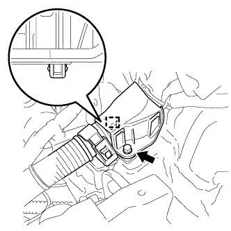
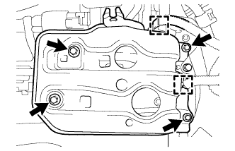
INSTALL PARK/NEUTRAL POSITION SWITCH ASSEMBLY
-
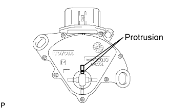
Align the protrusions of the park/neutral position switch.
-
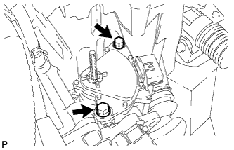
Install the park/neutral position switch to the control shaft with the 2 bolts.
- Torque:
- 5.4 N*m { 55 kgf*cm, 48 in.*lbf }
Note
-
Before installing the park/neutral position switch, remove any dirt or rust on the installation portion of the control shaft. Be sure to install the switch straight along the shaft while being careful not to deform the plate spring that supports the shaft. If the plate spring is deformed, the park/neutral position switch cannot be reinstalled correctly.
-
After installing the park/neutral position switch, confirm that the 2 protrusions on the switch are aligned.
-
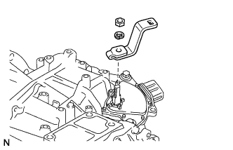
Install the control shaft lever to the control shaft with the nut and washer.
- Torque:
- 13 N*m { 130 kgf*cm, 9 ft.*lbf }
-
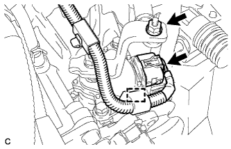
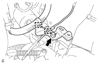
Connect the park/neutral position switch connector and clamp.
-
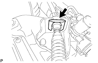
Connect the transmission control cable assembly to the control shaft lever with the nut.
- Torque:
- 12 N*m { 122 kgf*cm, 9 ft.*lbf }
Note
Before connecting the transmission control cable assembly, check that the park/neutral position switch and the shift lever are in N.
-
Connect the transmission control cable to the transmission control cable bracket with a new clip.
-
-
INSTALL ENGINE MOUNTING BRACKET LH
-
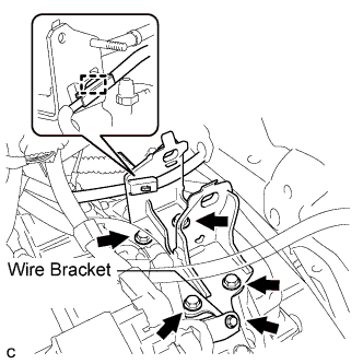
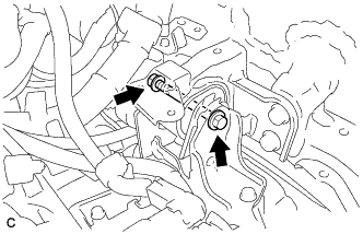
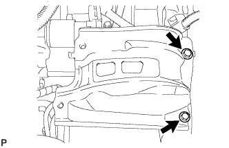
Install the engine mounting bracket LH to the automatic transaxle assembly with the 4 bolts.
- Torque:
- 64 N*m { 653 kgf*cm, 47 ft.*lbf }
-
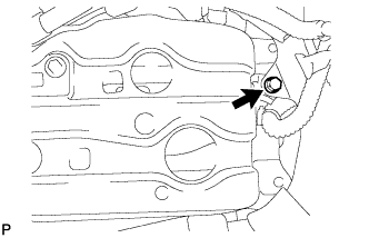
Install the engine wire bracket to the engine mounting bracket LH with the bolt.
-
Connect the clamp to the engine mounting bracket LH.
-
-
INSTALL ENGINE MOUNTING INSULATOR LH
-
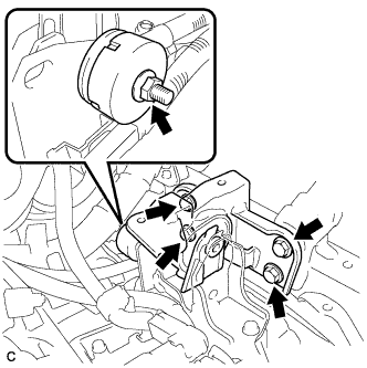
Install the engine mounting insulator LH with the 4 bolts.
- Torque:
- 95 N*m { 969 kgf*cm, 70 ft.*lbf }
-
Install the engine mounting damper with the nut.
- Torque:
- 15 N*m { 153 kgf*cm, 11 ft.*lbf }
-
Install the wire harness bracket to the engine mounting insulator LH with the bolt.
-
Connect the 2 clamps to the wire harness bracket.
-
Install the wire harness protector to the wire harness bracket with the bolt and clamp
-
Install the engine mounting insulator LH with the through bolt and nut.
- Torque:
- 56 N*m { 571 kgf*cm, 41 ft.*lbf }
-
-
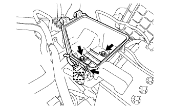
INSTALL BATTERY CARRIER SUPPORT
-
Install the battery carrier support with the 2 bolts.
- Torque:
- 20 N*m { 204 kgf*cm, 15 ft.*lbf }
-
-
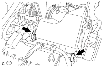
INSTALL BATTERY CARRIER
-
Insert the No. 2 air cleaner inlet to the battery carrier with the bolt.
- Torque:
- 8.0 N*m { 82 kgf*cm, 71 in.*lbf }
-
Install the front bracket with the 4 bolts.
- Torque:
- 20 N*m { 204 kgf*cm, 15 ft.*lbf }
-
Attach the 2 wire harness clamps.
-
-
INSTALL AIR CLEANER CASE
-
Install the air cleaner case with the 3 bolts.
- Torque:
- 7.0 N*m { 71 kgf*cm, 62 in.*lbf }
-
Connect the wire clamp.
-
Install the air cleaner filter element.
-
-
INSTALL AIR CLEANER CAP SUB-ASSEMBLY
-
Install the air cleaner cap sub-assembly to the air cleaner case with the 2 clamps.
-
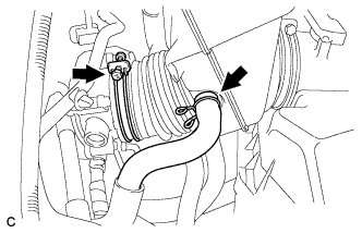
Connect the air cleaner hose to the throttle body with the hose clamp.
-
Connect the ventilation hose.
-
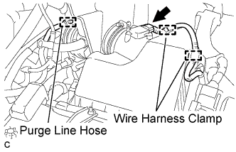
Connect the purge line hose.
-
Connect the 2 wire harness clamps and mass air flow meter connector.
-
-
INSTALL BATTERY
-
Install the battery, battery insulator and battery tray.
-
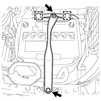
Install the battery clamp with the bolt and nut.
- Torque:
- Bolt
- 46 N*m { 469 kgf*cm, 34 ft.*lbf }
- Nut
- 4.9 N*m { 50 kgf*cm, 43 in.*lbf }
-
Connect the positive (+) cable to the battery positive (+) terminal.
- Torque:
- 7.6 N*m { 77 kgf*cm, 67 in.*lbf }
-
Connect the 2 wire clamps.
-
-
INSTALL RADIATOR COVER SUB-ASSEMBLY (for ALPHARD)
-
Install the radiator cover sub-assembly with the 4 clips.
-
-
INSTALL RADIATOR COVER SUB-ASSEMBLY (for VELLFIRE)
-
Install the radiator cover sub-assembly with the 4 clips.
-
-
INSTALL OUTER COWL TOP PANEL SUB-ASSEMBLY
-
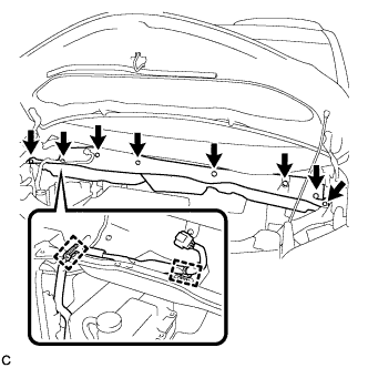
Install the outer cowl top panel with the 8 bolts.
- Torque:
- 8.8 N*m { 90 kgf*cm, 78 in.*lbf }
-
Connect the 2 clamps to the outer cowl top panel.
-
Remove the protective tape.
-
-
INSTALL BRAKE MASTER CYLINDER RESERVOIR BRACKET
-
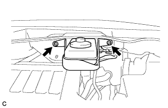
Install the brake master cylinder reservoir with bracket to the outer cowl top panel with the 2 nuts.
- Torque:
- 6.5 N*m { 66 kgf*cm, 58 in.*lbf }
-
-
INSTALL WINDSHIELD WIPER MOTOR AND LINK ASSEMBLY
-
CONNECT CABLE TO NEGATIVE BATTERY TERMINAL
Note
When disconnecting the cable, some systems need to be initialized after the cable is reconnected Click here.
-
INSPECT PARK/NEUTRAL POSITION SWITCH ASSEMBLY OPERATION
-
Apply the parking brake.
-
Turn the engine switch on (IG).
-
Depress the brake pedal and check that the engine starts when the shift lever is in N or P, but does not start in other positions.
-
Check that the back-up light comes on when the shift lever is moved to R, but the light does not operate in other positions. If the operation cannot be done as specified, check the park/neutral position switch for continuity.
-
-
INSPECT SHIFT LEVER POSITION
-
When moving the lever from P to R with the engine switch on (IG) and the brake pedal depressed, make sure that the shift lever moves smoothly and moves correctly into position.
-
Start the engine and make sure that the vehicle moves forward when moving the lever from N to D and moves rearward when moving the lever to R.
If the operation cannot be performed as specified, inspect the park/neutral position switch assembly and check the shift lever assembly installation condition.
-
-
ADJUST SHIFT LEVER POSITION
-
Apply the parking brake and move the shift lever to N.
-
Remove the instrument cluster finish panel assembly and center instrument cluster finish panel sub-assembly Click here.
-

Disconnect the end of the transmission control cable assembly from the shift lever assembly.
-
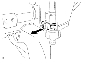
Pull out the stopper of the transmission control cable.
Note
Do not remove the stopper. If the stopper is removed, reinstall it to its original position.
-
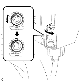
Rotate the nut counterclockwise approximately 180° and, while holding the nut in that position, disconnect the transmission control cable from the shift lever retainer.
Note
Do not over-rotate the nut as it will come off the internal spring and the transmission control cable will not be reusable.
-
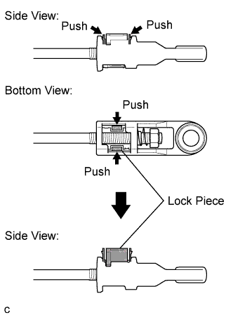
Push the 2 claws together at the top of the transmission control cable lock piece. While holding the 2 claws together, push the 2 lugs on the bottom of the lock piece toward each other and upward to pull out the lock piece.
-
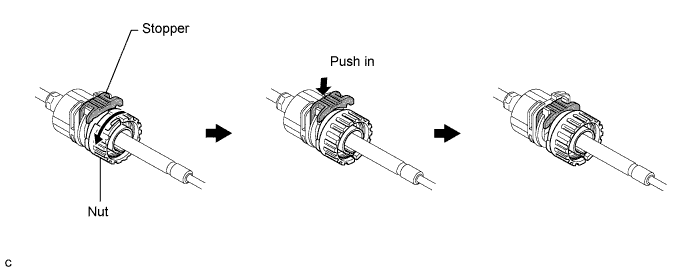
Turn the nut of the transmission control cable 180° counterclockwise. While holding the nut in place, push in the stopper until the stopper clicks twice.
-
Install the outer part of the transmission control cable to the shift lever retainer. Check that the spring is positioned at "A" and push in the stopper.
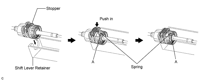
Tech Tips
If the stopper cannot be pushed in, slightly turn the nut clockwise and then push in the stopper again.
-
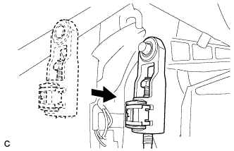
Install the cable end to the shift lever assembly.
Note
-
Check that the lock piece is pulled up.
-
Install the cable end all the way to the base of the pin.
-
-
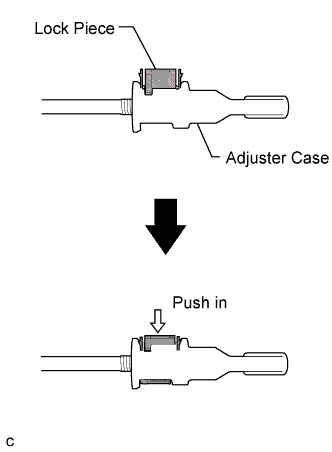
Push the lock piece into the adjuster case.
Note
Securely press in the lock piece until it locks.
-
After adjusting the shift lever position, check the operation and function of the shift lever. If there is a problem, adjust the position again.
-
Install the instrument cluster finish panel assembly and center instrument cluster finish panel sub- assembly Click here.
-